Preliminary Information
MT8924
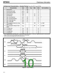
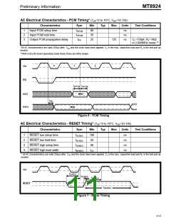
AC Electrical Characteristics - PCM Timing* (TOP=0 to 70°C; VDD=5V 5%)
Characteristics
Sym
Min
Typ
Max
Units
Test Conditions
1
2
3
Input PCM setup time
Input PCM hold time
tSPCM
tHPCM
tPD
80
35
25
ns
ns
ns
Output PCM propagation delay
125
CL=150pF, RL=1KΩ
in 2.048MHz mode **
*All AC characteristics are valid 250µs after VDD and the clock have been applied. CL is the max. capacitive load and RL is the test pull up
resistor.
**With Extra Bit Insert operating mode these times are 80ns longer.
0
1
2
Cki
F0i
t
t
SPCM HPCM
DSTi
MSB
t
PD
DSTo
MSB
Figure 6 - PCM Timing
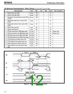
AC Electrical Characteristics - RESET Timing* (TOP=0 to 70°C; VDD=5V 5%)
Characteristics
Sym
Min
Typ
Max
Units
Test Conditions
1
2
3
4
RESET low setup time
RESET low hold time
RESET high setup time
RESET high level width
tSLRES
tHLRES
tSHRES
tWHRES
100
50
ns
ns
ns
ns
90
tCK
* All AC characteristics are valid 250µs after VDD and the clock have been applied. CL is the max. capacitive load and RL is the test pull up
resistor.
Cki
t
SLRES
t
HLRES
t
SHRES
RESET
t
WHRES
Figure 7 - Reset Timing
8-13

 MITEL [ MITEL NETWORKS CORPORATION ]