MH89790B
Preliminary Information
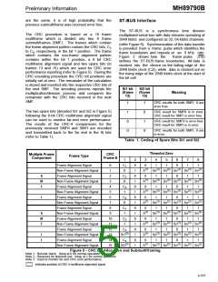
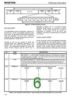
125µs
CHANNEL
CHANNEL
31
CHANNEL
30
CHANNEL
0
CHANNEL
31
0
• • •
Most
Significant
Least
Significant
Bit (Last)
BIT
0
BIT
7
BIT
6
BIT
5
BIT
3
BIT
2
BIT
1
BIT
4
Bit (First)
(8/2.048)µs
Figure 6 - ST-BUS Stream Format
illustrated in Figures 7 to 11. In common channel
signalling mode timeslot 16 becomes an active
channel. In this mode channel 16 on DSTi is
transmitted on timeslot 16 of the CEPT link
unaltered. This mode is activated by bit 5 of channel
31 of CSTi0.
Data Input (DSTi)
The MH89790B receives information channels on
the DSTi pin. Of the 32 available channels on this
serial input, 30 are defined as information channels.
They are channels 1-15 and 17-31. These 30
timeslots are the 30 telephone channels of the CEPT
format numbered 1-15 and 16-30.
Control Input 0 (CSTi0)
All the necessary control and signalling information
is input through the two control streams. Control
ST-BUS input number 0 (CSTi0) contains the control
information that is associated with each information
channel. Each control channel contains the per
channel digital attenuation information, the individual
Timeslot 0 and 16 are unused to allow the
synchronization and signalling information to be
inserted, from the Control Streams (CSTi0 and
CSTi1). The relationship between the input and
output ST-BUS stream and the CEPT line is
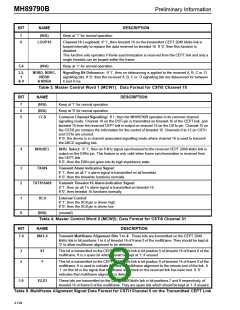
BIT
7
NAME
DATA
DESCRIPTION
Data Channel: If ‘1‘, then the controlled timeslot on the CEPT 2048 kbit/s link is treated as a
data channel; i.e., no ADI encoding or decoding is performed on transmission or reception,
and digital attenuation is disabled. If ‘0‘, then the state of the ADI pin determines whether or
not ADI encoding and decoding is performed.
6
LOOP
Per-Channel Loopback: If ‘1‘, then the controlled timeslot on the transmitted CEPT 2048
kbit/s link is looped internally to replace the data on the corresponding received timeslot. If
‘0‘, then this function is disabled. This function only operates if frame synchronization is
received from the CEPT link. If more than one channel is looped per frame only the first one
will be active.
5,4,3
RXPAD4,2,1
Receive Attenuation Pad: Per timeslot receive attenuation control bits.
RXPAD4
RXPAD2
RXPAD1
Gain (dB)
0
0
0
0
1
1
1
1
0
0
1
1
0
0
1
1
0
1
0
1
0
1
0
1
0
-1
-2
-3
-4
-5
-6
1
2,1,0
TXPAD4,2,1
Transmit Attenuation Pad: Per timeslot transmit attenuation control bits.
TXPAD4
TXPAD2
TXPAD1
Gain (dB)
0
0
0
0
1
1
1
1
0
0
1
1
0
0
1
1
0
0
1
0
1
0
1
0
0
-1
-2
-3
-4
-5
-6
1
Table 2. Per Channel Control Word: Data Format for CSTi0 Channels 0-14, and 16-30
4-192

 MITEL [ MITEL NETWORKS CORPORATION ]