Preliminary Information
MH89790B
are the same, it is of high probability that the
previous submultiframe was received error free.
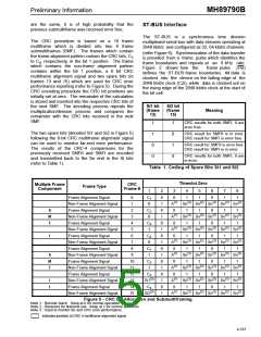
ST-BUS Interface
The ST-BUS is
multiplexed serial bus with data streams operating at
2048 kbit/s and configured as 32, 64 kbit/s channels
a
synchronous time division
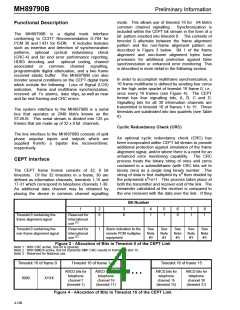
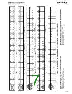
The CRC procedure is based on a 16 frame
multiframe which is divided into two 8 frame
submultiframes (SMF). The frames which contain
(refer Figure 6). Synchronization of the data transfer
is provided from a frame pulse which identifies the
frame boundaries and repeats at an 8 kHz rate.
the frame alignment pattern contain the CRC bits, C
1
to C respectively, in the bit 1 position. The frame
4,
which contains the non-frame alignment pattern
contains within the bit 1 position, a 6 bit CRC
multiframe alignment signal and two spare bits (in
frames 13 and 15) which are used for CRC error
performance reporting (refer to Figure 5). During the
CRC encoding procedure the CRC bit positions are
initially set at zero. The remainder of the calculation
is stored and inserted into the respective CRC bits of
the next SMF. The decoding process repeats the
multiplication/division process and compares the
remainder with the CRC bits received in the next
SMF.
Figure
2
shows how the
frame pulse (F0i)
defines the ST-BUS frame boundaries. All data is
clocked into the device on the falling edge of the
2048 kbit/s clock (C2i), while data is clocked out on
the rising edge of the 2048 kbit/s clock at the start of
the bit cell.
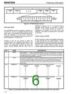
Si1 bit
(frame
13)
Si2 bit
(frame
15)
Meaning
CRC results for both SMFI, II are
error free.
1
1
0
0
1
0
1
0
The two spare bits (denoted Si1 and Si2 in Figure 5)
following the 6-bit CRC multiframe alignment signal
can be used to monitor far-end error performance.
The results of the CRC-4 comparisons for the
previously received SMFII and SMFI are encoded
and transmitted back to the far end in the Si bits
(refer to Table 1).
CRC result for SMFII is in error.
CRC result for SMFI is error free.
CRC result for SMFII is error free.
CRC result for SMFI is in error.
CRC results for both SMFI, II are
in error.
Table 1. Coding of Spare Bits Si1 and Si2
Timeslot Zero
Multiple Frame
Component
CRC
Frame Type
Frame #
1
2
0
1
0
1
0
1
0
1
0
1
0
1
0
1
0
1
3
0
4
1
5
1
6
0
7
1
8
1
Frame Alignment Signal
0
1
C
1
(1)
(2)
(2)
(2)
(2)
(2)
Non-Frame Alignment Signal
Frame Alignment Signal
0
A
Sn
Sn
Sn
Sn
Sn
S
M
F
2
C
0
1
1
0
1
1
2
(1)
(2)
(2)
(2)
(2)
(2)
Non-Frame Alignment Signal
Frame Alignment Signal
3
0
A
Sn
Sn
Sn
Sn
Sn
4
C
0
1
1
0
1
1
3
(1)
(2)
(2)
(2)
(2)
(2)
Non-Frame Alignment Signal
Frame Alignment Signal
5
1
A
Sn
Sn
Sn
Sn
Sn
I
6
C
0
1
1
0
1
1
4
(1)
(2)
(2)
(2)
(2)
(2)
Non-Frame Alignment Signal
Frame Alignment Signal
7
0
A
Sn
Sn
Sn
Sn
Sn
8
C
0
1
1
0
1
1
1
(1)
(2)
(2)
(2)
(2)
(2)
S
M
F
Non-Frame Alignment Signal
Frame Alignment Signal
9
1
A
Sn
Sn
Sn
Sn
Sn
10
11
12
13
14
15
C
0
1
1
0
1
1
2
(1)
(2)
(2)
(2)
(2)
(2)
Non-Frame Alignment Signal
Frame Alignment Signal
1
A
Sn
Sn
Sn
Sn
Sn
C
0
1
1
0
1
1
3
(3)
(1)
(2)
(2)
(2)
(2)
(2)
I
I
Non-Frame Alignment Signal
Frame Alignment Signal
Si1
A
Sn
Sn
Sn
Sn
Sn
C
0
1
1
0
1
1
4
(3)
(1)
(2)
(2)
(2)
(2)
(2)
Non-Frame Alignment Signal
Si2
A
Sn
Sn
Sn
Sn
Sn
Figure 5 - CRC Bit Allocation and Submultiframing
Note 1 : Remote Alarm. Keep at 0 for normal operation.
Note 2 : Reserved for National use. Keep at 1 for normal operation.
Note 3 : Used to monitor far-end CRC error performance.
indicates position of CRC-4 multiframe alignment signal
4-191

 MITEL [ MITEL NETWORKS CORPORATION ]