MH89790B
Preliminary Information
NC
NC
LOS
NC
NC
40
39
38
37
36
IC
E2o
VDD
RxA
RxT
RxR
2
3
4
5
6
7
NC
35
34
33
32
31
30
29
28
27
26
25
24
23
22
21
NC
VSS
NC
DSTo
NC
OUTB
NC
RxMF
TxMF
OUTA
PADo
TxG
PADi
VSS
RxB
NC
8
9
CSTi1
10
11
12
13
14
15
16
17
18
19
20
CSTi0
E8Ko
XCtl
XSt
CSTo
ADl
DSTi
C2i
E2o
F0i
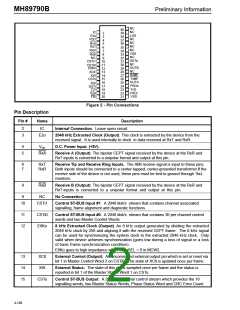
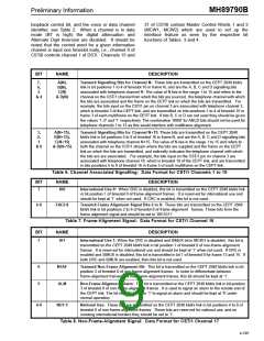
Figure 2 - Pin Connections
Description
Pin Description
Pin #
Name
2
3
IC
Internal Connection. Leave open circuit.
E2o
2048 kHz Extracted Clock (Output): This clock is extracted by the device from the
received signal. It is used internally to clock in data received at RxT and RxR.
4
5
VDD
D.C. Power Input. (+5V).
RxA
Receive A (Output): The bipolar CEPT signal received by the device at the RxR and
RxT inputs is converted to a unipolar format and output at this pin.
6
7
RxT
RxR
Receive Tip and Receive Ring Inputs. The AMI receive signal is input to these pins.
Both inputs should be connected to a center-tapped, center-grounded transformer.If the
receive side of the device is not used, these pins must be tied to ground through 1kΩ
resistors.
8
RxB
Receive B (Output): The bipolar CEPT signal received by the device at the RxR and
RxT inputs is converted to a unipolar format and output at this pin.
9
NC
No Connection.
10
CSTi1
Control ST-BUS Input #1: A 2048 kbit/s stream that contains channel associated
signalling, frame alignment and diagnostic functions.
11
12
CSTi0
E8Ko
Control ST-BUS Input #0: A 2048 kbit/s stream that contains 30 per channel control
words and two Master Control Words.
8 kHz Extracted Clock (Output): An 8 kHz output generated by dividing the extracted
2048 kHz clock by 256 and aligning it with the received CEPT frame. The 8 kHz signal
can be used for synchronizing the system clock to the extracted 2048 kHz clock. Only
valid when device achieves synchronization (goes low during a loss of signal or a loss
of basic frame synchronization condition).
E8Ko goes to high impedance when 8kHzSEL = 0 in MCW2.
13
14
15
XCtl
XSt
External Control (Output): An uncommitted external output pin which is set or reset via
bit 1 in Master Control Word 2 on CSTi0. The state of XCtl is updated once per frame.
External Status: The state of this pin is sampled once per frame and the status is
reported in bit 1 of the Master Status Word 1 on CSTo.
CSTo
Control ST-BUS Output: A 2048 kbit/s serial control stream which provides the 16
signalling words, two Master Status Words, Phase Status Word and CRC Error Count.
4-188

 MITEL [ MITEL NETWORKS CORPORATION ]