Preliminary Information
MH88620BR
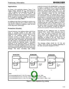
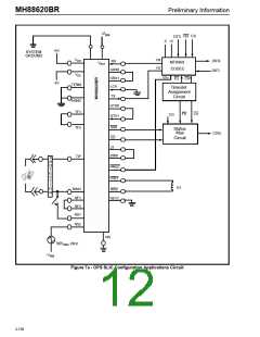
protection circuitry for the MH88620BR, as illustrated
in Figure 7, consists of PTC1, PTC2 and clamping
diodes D1 to D4. During a fault condition, the diodes
clamp the overvolt Ground and -VBAT. PTC1 and
PTC2 current limit as their resistance increases with
power dissipation caused by the over-voltage/
over-current condition. The ground that D1 and D3
are connected to, must be an EDG (energy dumping
ground) which is connected to the chassis or system
ground. This is a seperate conductor from LPGND or
AGND on the line card PCB. D2 and D4 conduct the
energy into a -VBAT supply which is a seperate
conductor from the -VBAT feed supply to the SLICs.
A power MOSFET circuit as shown in Figure 8, can
be used to divert the energy normally dumped into
-VBAT, the EDG conductor. Usually one MOSFET
circuit can be used for 16 SLICs or per line card.
Applications
As shown in the application diagram, Figure 7, the
ringing voltage, typically 80 VRMS 25Hz biased at
-VBAT, is applied to the subscriber line through an
external relay, K1, K1 is a DPST 2-form-C, EM
(electro-mechanical) relay which switches protection
diodes D3 and D4 out when Ringing is switched in,
K1 is enabled by applying a logic low level to the
relay driver control input, RNGC.
An additional relay driver is provided to control an In/
Out Test Bus relay, K2. K2 is a DPST 2-form-C, EM
relay which is enabled by applying a logic low level
to the relay driver control input.
Protection Circuitry
Depending on the additional level of protection
required, PRO1 and/or PRO2 protectors may be
used. These are used to protect the SLICs Ring
sense resistor and/or Ring generator, from being
damaged if a fault condition occurs during the
application of Ringing to the line. PRO2 can be
implemented using two back to back zener diodes,
or an equivalent transcient suppressor.
Primary protection, from lightning strikes and AC line
faults, is normally located in the MDF (main
distribution feeder) which is located external to the
PABX or CO switching system. The primary
protection circuitry is normally housed in a 5-pin
connector and consists of either carbon blocks, with
spark gaps (older technology), gas discharge limits
the high voltage to approximately 300 to 500 volts
before entering the switching system. Secondary
protection, in the switching system, is required to
further limit these high voltages/ currents. Secondary
protection is normally implemented on each line card
and is designed to protect the SLICs from permanent
damage. The basic secondary high voltage
The clamping voltage should be >16 Vdc and
<26Vdc. PRO2 may not be required depending on
the value and power dissipation of PRO1.
MH88620BR
MH88620BR
MH88620BR
24
24
24
23
Z2
Z2
Z2
23
R
R
R
Internal
Internal
Internal
8500 Ω
Z1
Z1
Z1
8500Ω
8500Ω
R
External
External
340Ω
0.22µF
B.
A.
C.
Notes
a) to accommodate the use of 2 x 25Ω PTCs, connect Z1 and Z2 together, Z = 900Ω.
in
b) to accommodate the use of 2 x 8Ω PTCs, connect 340Ω between Z1 and Z2 = 900Ω.
c) to accommodate the use of 2 x 25Ω PTCs, connect 0.22µF between Z1 and Z2 = 900Ω + 2.2µF.
Figure 3 - Input Impedance (Z ) setting
in
2-153

 MITEL [ MITEL NETWORKS CORPORATION ]