Preliminary Information
MH88620BR
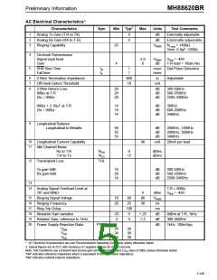
AC Electrical Characteristics*
‡
Characteristics
Sym
Min
Typ
Max
Units
Test Comments
1
2
3
Analog Tx Gain (T-R to TX)
Analog Rx Gain (RX to T-R)
Ringing Capability
0
0
dB
dB
Externally adjustable
Externally adjustable
25
VRMS
RLoop = 1400Ω
Term. 6.8µF +200Ω
4
5
On-hook Transmission
Signal input level
Gain
2.0
8
VRMS
dB
V
Bat = -48V
4
T-R load = 10Ωk min.
SHK Rise Time
Fall time
tR
tF
1
1
msec Dial Pulse Detection
msec
6
7
8
2 Wire Termination Impedance
Off-Hook Detect Threshold
900
10
Ω
Adjustable
mA
2-Wire Return Loss
900Ω at T-R
Zin = 900Ω
20
26
20
dB
dB
dB
300-500Hz
500-2500Hz
2500-3400Hz
900Ω + 2.16µF at T-R
Zin = 900Ω
14
18
14
dB
dB
dB
300Hz
600-2000Hz
3400Hz
9
Longitudinal Balance
Longitudinal to Metallic
58
55
53
dB
dB
dB
2000Hz, 1000Hz
2000Hz, 3000Hz
3400Hz
10
11
Longitudinal Current Capability
40
mA
20mA per lead
Idle Channel Noise
Rx to T-R
NCR
NCX
8
12
dBrnc
dBrnc
T-R to Tx
12
Transhybrid Loss
THL
Tx gain 0dB
Rx gain 0dB
16
20
16
dB
dB
dB
300-500Hz
500-2500Hz
2500-3400Hz
13
14
Analog Signal Overload Level at
TIP and RING
T-R = 900Ω
VBat = -48V
4
dBm
VRMS
Hz
15
16
17
18
19
20
Ringing Signal Voltage
Ringing Frequency
70
20
80
25
100
0
90
30
Ring Trip Delay
ms
Absolute Gain variation
Relative Gain, reference to 1kHz
-25
-2
+.25
+.2
dB
0dBm at T-R, 1kHz
300-3400Hz
0
dB
Power Supply Rejection Ratio
PSRR
dB
1kHz, 100mVpp
VBat
VDD
VEE
24
24
24
30
30
30
* AC Electrical Characteristics are over Recommended Operating Conditions unless otherwise stated.
‡ Typical figures are at 25°C with nominal + 5V supplies and are for design aid only.
Note: Test Conditions use a transmit and receive gain set to 0dB default and a Z value of 900Ω unless otherwise stated.
in
“Ref” indicates reference impedance which is equivalent to the termination impedance.
“Net” indicates network balance impedance.
2-149

 MITEL [ MITEL NETWORKS CORPORATION ]