SDA 9380 - B21
Preliminary Data Sheet
System description
Vertical blanking start (VBS), RGB ref. pulse pos. (RPP), Vertical blanking end (VBE):
The control item RPP defines the position of the three reference pulses for
R, G, B:
Red ref. pulse = RPP + 16; (odd field)
Green ref. pulse = RPP + 17; (odd field)
Blue ref. pulse = RPP + 18; (odd filed)
(def. value 20)
(def. value 21)
(def. value 22)
If bit BSE (Blanking Select Enable) = 0 the control item RPP is replaced by its
default value (=4). So the R, G, B ref. pulses are generated in line 20, 21, 22 in
the odd field rsp. line 21, 22 , 23 in the even field (see diagram below).
VBS defines the start as well of the internal vertical blanking pulse VBL as of
the output signal VBLO. The end of the internal signal VBL is defined by RPP
and VBE. This also applies to the end of VBLO with one exception. There is at
least one line between the cutoff/white level measurement line for blue and the
end of VBLO. The vertical component of the SCP signal is always identical
with the internal vertical blanking pulse VBL.
Both VBL as well as VBLO are synchronized with the leading edge of HSYNC.
It always starts and stops at the beginning of line and never in the center.
Therefore the end and width of VBL is one line more in the even field than in
the odd field.
If the vertical drive signals VD+, VD- are clipped in zoom mode (vertical
aspect > 0) at the top and bottom of the screen the vertical blanking pulse is
extended to blank all lines in this area without any additional programming.
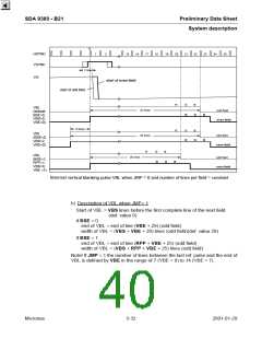
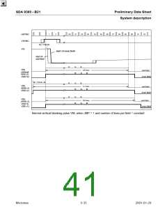
a) Description of VBL when JMP= 0
Start of VBL = VBS lines before the first complete line of the next field
(def. value 0)
if BSE = 0
end of VBL = end of line (VBE + 22) (odd field)
width of VBL = (VBS + VBE + 22) lines (odd field)(def. value 22)
After power on the control bit BSE is 0, also VBS = 0 and VBE = 0. Therefore
22 lines (odd field) will be blanked before any programming of the IC.
if BSE = 1
end of VBL = end of line (RPP + VBE + 18) (odd field)
width of VBL = (VBS + RPP + VBE + 18) lines (odd field)
The number of lines between the last ref. pulse and the end of VBL is defined
by VBE in the range of 0 (VBE = 0) to 7 (VBE = 7).
If VBS = 0 (minimum value) VBL starts (point A in fig. below) 0...0.5 line (new
odd field) or 0.5...1 line (new even field) prior to the vertical flyback.
Micronas
5-31
2001-01-29

 MICRONAS [ MICRONAS ]