SDA 9380 - B21
Preliminary Data Sheet
System description
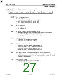
The Vertical sync control byte includes the following bits:
X
X
SSC
X
NI
X
X
X
- SSC:
Sandcastle without VBL
0: output SCP with VBL component
1: output SCP without VBL component
- NI:
Non interlace
0: interlace depends on source
1: no interlace
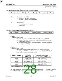
The PWM control byte includes the following bits:
PWMC5
PWMC4
PWMC3
PWMC2
PWMC1
PWMC0
PWMS1
PWMS0
- PWMS1..
PWMS0: PWM select
x0: same duty cycle in each line selected (adjustable by PWMC)
01: positive V-parabola after external integration available (amplitude
adjustable by PWMC)
11: negative V-parabola after external integration available (amplitude
adjustable by PWMC)
- PWMC5..
PWMC0: PWM control
These bits control either the duty cycle or the parabola amplitude
depending on PWMS0 according to the following table (if PWMS0 = 0
also PWMS1 defines the the duty cycle):
PWMC5...PWMC0
Duty cycle
Amplitude of V-parabola
(PWMS0 = 0)
(ext. integration, PWMS0 = 1)
1)
0.46 * (VOH -VOL
0.58 * (VOH -VOL
0.69 * (VOH -VOL
0.81 * (VOH -VOL
0.91 * (VOH -VOL
)
)
)
)
)
100000
110000
000000
010000
011111
PWMS1/108
(32+PWMS1)/108
(64+PWMS1)/108
(96+PWMS1)/108
1
1)
1)
1)
1)
1)
V
: PWM output High level, VOL: PWM output Low level
OH
The PWM output may be used as switching output when PWMS0 = 0. If PWMC = 100000
and PWMS1 = 0 the output is Low. If PWMC = 011111 the output is continously High.
Micronas
5-20
2001-01-29

 MICRONAS [ MICRONAS ]