PIC24FJ64GA104 FAMILY
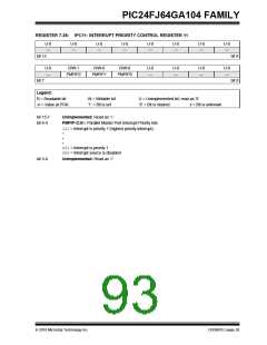
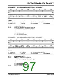
REGISTER 7-30: IPC18: INTERRUPT PRIORITY CONTROL REGISTER 18
U-0
—
U-0
—
U-0
—
U-0
—
U-0
—
U-0
—
U-0
—
U-0
—
bit 15
bit 8
U-0
—
U-0
—
U-0
—
U-0
—
U-0
—
R/W-1
R/W-0
R/W-0
LVDIP2
LVDIP1
LVDIP0
bit 7
bit 0
Legend:
R = Readable bit
-n = Value at POR
W = Writable bit
‘1’ = Bit is set
U = Unimplemented bit, read as ‘0’
‘0’ = Bit is cleared x = Bit is unknown
bit 15-3
bit 2-0
Unimplemented: Read as ‘0’
LVDIP<2:0>: Low-Voltage Detect Interrupt Priority bits
111= Interrupt is priority 7 (highest priority interrupt)
•
•
•
001= Interrupt is priority 1
000= Interrupt source is disabled
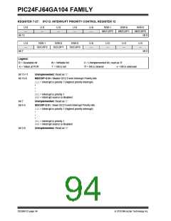
REGISTER 7-31: IPC19: INTERRUPT PRIORITY CONTROL REGISTER 19
U-0
—
U-0
—
U-0
—
U-0
—
U-0
—
U-0
—
U-0
—
U-0
—
bit 15
bit 8
bit 0
U-0
—
R/W-1
R/W-0
R/W-0
U-0
—
U-0
—
U-0
—
U-0
—
CTMUIP2
CTMUIP1
CTMUIP0
bit 7
Legend:
R = Readable bit
-n = Value at POR
W = Writable bit
‘1’ = Bit is set
U = Unimplemented bit, read as ‘0’
‘0’ = Bit is cleared x = Bit is unknown
bit 15-7
bit 6-4
Unimplemented: Read as ‘0’
CTMUIP<2:0>: CTMU Interrupt Priority bits
111= Interrupt is priority 7 (highest priority interrupt)
•
•
•
001= Interrupt is priority 1
000= Interrupt source is disabled
bit 3-0
Unimplemented: Read as ‘0’
2010 Microchip Technology Inc.
DS39951C-page 97

 MICROCHIP [ MICROCHIP ]