PIC24FJ64GA104 FAMILY
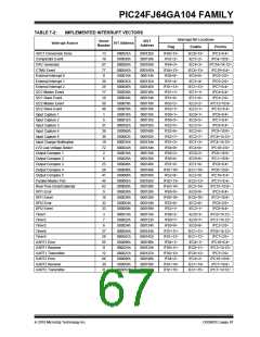
The interrupt sources are assigned to the IFSx, IECx
and IPCx registers in the order of their vector numbers,
as shown in Table 7-2. For example, the INT0 (External
Interrupt 0) is shown as having a vector number and a
natural order priority of 0. Thus, the INT0IF status bit is
found in IFS0<0>, the INT0IE enable bit in IEC0<0>
and the INT0IP<2:0> priority bits in the first position of
IPC0 (IPC0<2:0>).
7.3
Interrupt Control and Status
Registers
The PIC24FJ64GA104 family of devices implements
the following registers for the interrupt controller:
• INTCON1
• INTCON2
• IFS0 through IFS4
• IEC0 through IEC4
Although they are not specifically part of the interrupt
control hardware, two of the CPU control registers con-
tain bits that control interrupt functionality. The ALU
STATUS Register (SR) contains the IPL<2:0> bits
(SR<7:5>); these indicate the current CPU interrupt
priority level. The user may change the current CPU
priority level by writing to the IPL bits.
• IPC0 through IPC20 (except IPC13, IPC14 and
IPC17)
• INTTREG
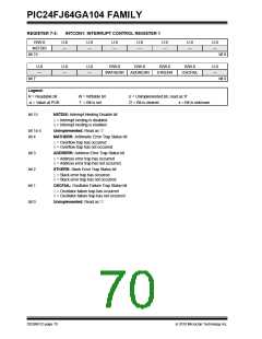
Global interrupt control functions are controlled from
INTCON1 and INTCON2. INTCON1 contains the Inter-
rupt Nesting Disable (NSTDIS) bit, as well as the
control and status flags for the processor trap sources.
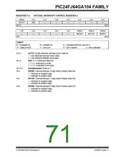
The INTCON2 register controls the external interrupt
request signal behavior and the use of the Alternate
Interrupt Vector Table.
The CORCON register contains the IPL3 bit, which,
together with IPL<2:0>, indicates the current CPU
priority level. IPL3 is a read-only bit so that trap events
cannot be masked by the user software.
The interrupt controller has the Interrupt Controller Test
Register (INTTREG) that displays the status of the
interrupt controller. When an interrupt request occurs,
its associated vector number and the new interrupt
priority level are latched into INTTREG.
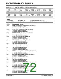
The IFSx registers maintain all of the interrupt request
flags. Each source of interrupt has a status bit which is
set by the respective peripherals, or an external signal,
and is cleared via software.
The IECx registers maintain all of the interrupt enable
bits. These control bits are used to individually enable
interrupts from the peripherals or external signals.
This information can be used to determine a specific
interrupt source if a generic ISR is used for multiple
vectors – such as when ISR remapping is used in boot-
loader applications. It also could be used to check if
another interrupt is pending while in an ISR.
The IPCx registers are used to set the interrupt priority
level for each source of interrupt. Each user interrupt
source can be assigned to one of eight priority levels.
All interrupt registers are described in Register 7-1
through Register 7-32, on the following pages.
DS39951C-page 68
2010 Microchip Technology Inc.

 MICROCHIP [ MICROCHIP ]