PIC24FJ64GA104 FAMILY
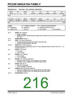
REGISTER 20-1: CRCCON1: CRC CONTROL REGISTER 1
R/W-0
U-0
—
R/W-0
CSIDL
R-0
R-0
R-0
R-0
R-0
CRCEN
VWORD4
VWORD3
VWORD2
VWORD1
VWORD0
bit 15
bit 8
R-0, HCS
CRCFUL
R-1, HCS
CRCMPT
R/W-0
R/W-0, HC
CRCGO
R/W-0
U-0
—
U-0
—
U-0
—
CRCISEL
LENDIAN
bit 7
bit 0
Legend:
HC = Hardware Clearable bit
W = Writable bit
HCS = Hardware Clearable/Settable bit
U = Unimplemented bit, read as ‘0’
R = Readable bit
-n = Value at POR
‘1’ = Bit is set
‘0’ = Bit is cleared
x = Bit is unknown
bit 15
CRCEN: CRC Enable bit
1= Module is enabled
0= Module is enabled. All state machines, pointers and CRCWDAT/CRCDAT are reset; other SFRs are
NOT reset.
bit 14
bit 13
Unimplemented: Read as ‘0’
CSIDL: CRC Stop in Idle Mode bit
1= Discontinue module operation when device enters Idle mode
0= Continue module operation in Idle mode
bit 12-8
bit 7
VWORD<4:0>: Pointer Value bits
Indicates the number of valid words in the FIFO. Has a maximum value of 8 when PLEN<3:0> > 7, or
16 when PLEN<3:0> 7.
CRCFUL: FIFO Full bit
1= FIFO is full
0= FIFO is not full
bit 6
CRCMPT: FIFO Empty Bit
1= FIFO is empty
0= FIFO is not empty
bit 5
CRCISEL: CRC interrupt Selection bit
1= Interrupt on FIFO is empty; CRC calculation is not complete
0= Interrupt on shift is complete and CRCWDAT result is ready
bit 4
CRCGO: Start CRC bit
1= Start CRC serial shifter
0= CRC serial shifter is turned off
bit 3
LENDIAN: Data Shift Direction Select bit
1= Data word is shifted into the CRC starting with the LSb (little endian)
0= Data word is shifted into the CRC starting with the MSb (big endian)
bit 2-0
Unimplemented: Read as ‘0’
DS39951C-page 216
2010 Microchip Technology Inc.

 MICROCHIP [ MICROCHIP ]