PIC18F2480/2580/4480/4580
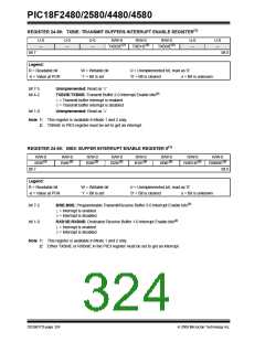
REGISTER 24-59: TXBIE: TRANSMIT BUFFERS INTERRUPT ENABLE REGISTER(1)
U-0
—
U-0
—
U-0
—
R/W-0
TXB2IE(2)
R/W-0
TXB1IE(2)
R/W-0
TXB0IE(2)
U-0
—
U-0
—
bit 7
bit 0
Legend:
R = Readable bit
-n = Value at POR
W = Writable bit
‘1’ = Bit is set
U = Unimplemented bit, read as ‘0’
‘0’ = Bit is cleared x = Bit is unknown
bit 7-5
bit 4-2
Unimplemented: Read as ‘0’
TXB2IE:TXB0IE: Transmit Buffer 2-0 Interrupt Enable bits(2)
1= Transmit buffer interrupt is enabled
0= Transmit buffer interrupt is disabled
bit 1-0
Unimplemented: Read as ‘0’
Note 1: This register is available in Mode 1 and 2 only.
2: TXBnIE in PIE3 register must be set to get an interrupt.
REGISTER 24-60: BIE0: BUFFER INTERRUPT ENABLE REGISTER 0(1)
R/W-0
R/W-0
R/W-0
R/W-0
R/W-0
R/W-0
R/W-0
R/W-0
B5IE(2)
B4IE(2)
B3IE(2)
B2IE(2)
B1IE(2)
B0IE(2)
RXB1IE(2)
RXB0IE(2)
bit 7
bit 0
Legend:
R = Readable bit
-n = Value at POR
W = Writable bit
‘1’ = Bit is set
U = Unimplemented bit, read as ‘0’
‘0’ = Bit is cleared x = Bit is unknown
bit 7-2
bit 1-0
B5IE:B0IE: Programmable Transmit/Receive Buffer 5-0 Interrupt Enable bits(2)
1= Interrupt is enabled
0= Interrupt is disabled
RXB1IE:RXB0IE: Dedicated Receive Buffer 1-0 Interrupt Enable bits(2)
1= Interrupt is enabled
0= Interrupt is disabled
Note 1: This register is available in Mode 1 and 2 only.
2: Either TXBnIE or RXBnIE in the PIE3 register must be set to get an interrupt.
DS39637D-page 324
© 2009 Microchip Technology Inc.

 MICROCHIP [ MICROCHIP ]