PIC18F2480/2580/4480/4580
24.2.5
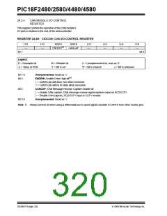
CAN MODULE I/O CONTROL
REGISTER
This register controls the operation of the CAN module’s
I/O pins in relation to the rest of the microcontroller.
REGISTER 24-55: CIOCON: CAN I/O CONTROL REGISTER
U-0
—
U-0
—
R/W-0
ENDRHI(1)
R/W-0
U-0
—
U-0
—
U-0
—
U-0
—
CANCAP
bit 7
bit 0
Legend:
R = Readable bit
-n = Value at POR
W = Writable bit
‘1’ = Bit is set
U = Unimplemented bit, read as ‘0’
‘0’ = Bit is cleared x = Bit is unknown
bit 7-6
bit 5
Unimplemented: Read as ‘0’
ENDRHI: Enable Drive High bit(1)
1= CANTX pin will drive VDD when recessive
0= CANTX pin will be tri-state when recessive
bit 4
CANCAP: CAN Message Receive Capture Enable bit
1= Enable CAN capture, CAN message receive signal replaces input on RC2/CCP1
0= Disable CAN capture, RC2/CCP1 input to CCP1 module
bit 3-0
Unimplemented: Read as ‘0’
Note 1: Always set this bit when using a differential bus to avoid signal crosstalk in CANTX from other nearby pins.
DS39637D-page 320
© 2009 Microchip Technology Inc.

 MICROCHIP [ MICROCHIP ]