PIC18F2480/2580/4480/4580
Writing a new value to the SPBRGH:SPBRG registers
causes the BRG timer to be reset (or cleared). This
ensures the BRG does not wait for a timer overflow
before outputting the new baud rate.
19.1 Baud Rate Generator (BRG)
The BRG is a dedicated, 8-bit or 16-bit generator that
supports both the Asynchronous and Synchronous
modes of the EUSART. By default, the BRG operates
in 8-bit mode; setting the BRG16 bit (BAUDCON<3>)
selects 16-bit mode.
Note:
BRG value of ‘0’ is not supported.
19.1.1
OPERATION IN POWER-MANAGED
MODES
The SPBRGH:SPBRG register pair controls the period
of a free running timer. In Asynchronous mode, bits
BRGH (TXSTA<2>) and BRG16 (BAUDCON<3>) also
control the baud rate. In Synchronous mode, BRGH is
ignored. Table 19-1 shows the formula for computation
of the baud rate for different EUSART modes which
only apply in Master mode (internally generated clock).
The device clock is used to generate the desired baud
rate. When one of the power-managed modes is
entered, the new clock source may be operating at a
different frequency. This may require an adjustment to
the value in the SPBRG register pair.
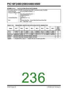
Given the desired baud rate and FOSC, the nearest
integer value for the SPBRGH:SPBRG registers can be
calculated using the formulas in Table 19-1. From this,
the error in baud rate can be determined. An example
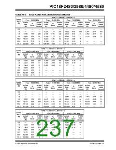
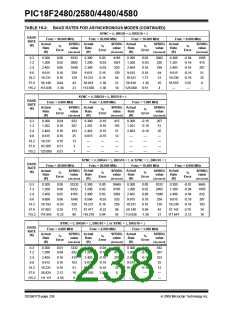
calculation is shown in Example 19-1. Typical baud
rates and error values for the various Asynchronous
modes are shown in Table 19-2. It may be
advantageous to use the high baud rate (BRGH = 1) or
the 16-bit BRG to reduce the baud rate error, or
achieve a slow baud rate for a fast oscillator frequency.
19.1.2
SAMPLING
The data on the RX pin is sampled three times by a
majority detect circuit to determine if a high or a low
level is present at the RX pin when SYNC is clear or
when BRG16 and BRGH are both not set. The data on
the RX pin is sampled once when SYNC is set or when
BRGH16 and BRGH are both set.
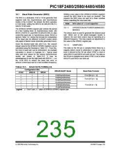
TABLE 19-1: BAUD RATE FORMULAS
Configuration Bits
BRG/EUSART Mode
Baud Rate Formula
SYNC
BRG16
BRGH
0
0
0
0
1
1
0
0
1
1
0
1
0
1
0
1
x
x
8-bit/Asynchronous
8-bit/Asynchronous
16-bit/Asynchronous
16-bit/Asynchronous
8-bit/Synchronous
16-bit/Synchronous
FOSC/[64 (n + 1)]
FOSC/[16 (n + 1)]
FOSC/[4 (n + 1)]
Legend: x= Don’t care, n = value of SPBRGH:SPBRG register pair
© 2009 Microchip Technology Inc.
DS39637D-page 235

 MICROCHIP [ MICROCHIP ]