PIC18CXX2
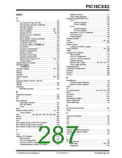
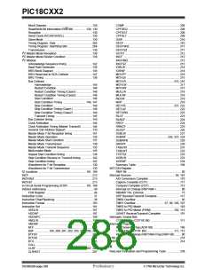
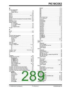
Assignment (PSA Bit) ................................................95
Rate Select (PS2:PS0 Bits) .......................................95
Switching Between Timer0 and WDT ........................95
Power-on Reset (POR) .............................................. 24, 181
Oscillator Start-up Timer (OST) ......................... 24, 181
Power-up Timer (PWRT) ................................... 24, 181
Time-out Sequence ....................................................25
Time-out Sequence on Power-up ........................30, 31
Timing Diagram ........................................................256
Prescaler, Capture ...........................................................111
Prescaler, Timer0 ...............................................................95
Assignment (PSA Bit) ................................................95
Rate Select (PS2:PS0 Bits) .......................................95
Switching Between Timer0 and WDT ........................95
Prescaler, Timer1 ...............................................................98
Prescaler, Timer2 .............................................................115
PRO MATE II Universal Programmer ............................237
Product Identification System ...........................................297
Program Counter
PCL Register ..............................................................37
PCLATH Register ......................................................37
Program Memory ...............................................................33
Interrupt Vector ..........................................................33
Reset Vector ..............................................................33
Program Verification .........................................................189
Programming, Device Instructions ...................................191
PWM (CCP Module) .........................................................114
Block Diagram ..........................................................114
CCPR1H:CCPR1L Registers ...................................115
Duty Cycle ................................................................115
Example Frequencies/Resolutions ..........................116
Output Diagram ........................................................114
Period .......................................................................115
Set-Up for PWM Operation ......................................116
TMR2 to PR2 Match ........................................ 102, 115
Simplified Block Diagram of On-Chip Reset Circuit ........... 23
Slave Select Synchronization .......................................... 125
Slave Select, SS .............................................................. 121
SLEEP ............................................................. 181, 187, 226
Software Simulator (MPLAB-SIM) ................................... 236
Special Features of the CPU ................................... 175, 181
Special Function Registers ................................................ 40
SPI
Master Mode ............................................................ 124
Serial Clock .............................................................. 121
Serial Data In ........................................................... 121
Serial Data Out ........................................................ 121
Slave Select ............................................................. 121
SPI clock .................................................................. 124
SPI Mode ................................................................. 121
SPI Master/Slave Connection .......................................... 123
SPI Module
Master/Slave Connection ......................................... 123
Slave Mode .............................................................. 125
Slave Select Synchronization .................................. 125
Slave Synch Timnig ................................................. 125
Slave Timing with CKE = 0 ...................................... 126
Slave Timing with CKE = 1 ...................................... 126
SS .................................................................................... 121
SSP .................................................................................. 117
Block Diagram (SPI Mode) ...................................... 121
SPI Mode ................................................................. 121
SSPBUF .................................................................. 124
SSPCON1 ............................................................... 119
SSPCON2 ............................................................... 120
SSPSR .................................................................... 124
SSPSTAT ................................................................ 118
TMR2 Output for Clock Shift ............................ 102, 103
SSP Module
SPI Master Mode ..................................................... 124
SPI Master./Slave Connection ................................. 123
SPI Slave Mode ....................................................... 125
SSPCON1 ........................................................................ 119
SSPCON2 ........................................................................ 120
SSPOV ............................................................................ 139
SSPSTAT ........................................................................ 118
SSPSTAT Register
Q
Q-Clock ............................................................................115
R
RCSTA Register
SPEN Bit ..................................................................151
Register File .......................................................................40
Registers
R/W Bit ............................................................ 129, 130
SUBLW ............................................................................ 227
SUBWF ............................................................ 226, 227, 228
SUBWFB ......................................................................... 229
SWAPF ............................................................................ 230
SSPSTAT .................................................................118
T1CON
Diagram ...........................................................105
Section .............................................................105
Reset .......................................................................... 23, 181
Timing Diagram ........................................................256
RETFIE .................................................................... 221, 222
RETLW .............................................................................222
RETURN ..........................................................................223
Revision History ...............................................................285
RLCF ................................................................................223
RLNCF .............................................................................224
RRCF ...............................................................................224
RRNCF .............................................................................225
T
TABLRD ........................................................................... 231
TABLWT .......................................................................... 232
Timer Modules
Timer1
Block Diagram ................................................. 106
Timer0 ................................................................................ 93
Clock Source Edge Select (T0SE Bit) ....................... 95
Clock Source Select (T0CS Bit) ................................. 95
Overflow Interrupt ...................................................... 95
Timing Diagram ....................................................... 257
Timer1 ........................................................................ 97, 105
Block Diagram ........................................................... 98
Oscillator .............................................. 97, 99, 105, 107
Overflow Interrupt ................................ 97, 99, 105, 107
Special Event Trigger (CCP) ..................... 99, 107, 112
Timing Diagram ....................................................... 257
TMR1H Register ................................................ 97, 105
S
SCK ..................................................................................121
SDI ...................................................................................121
SDO .................................................................................121
SEEVAL Evaluation and Programming System ............238
Serial Clock, SCK .............................................................121
Serial Data In, SDI ...........................................................121
Serial Data Out, SDO .......................................................121
DS39026B-page 290
Preliminary
7/99 Microchip Technology Inc.
 MICROCHIP [ MICROCHIP ]
