PIC18CXX2
Software Interrupt .................................................... 111
Timer1 Mode Selection ............................................ 111
Capture/Compare/PWM (CCP) ....................................... 109
CCP1 ....................................................................... 110
CCPR1H Register ........................................... 110
INDEX
A
A/D ................................................................................... 167
A/D Converter Flag (ADIF Bit) ................................. 169
A/D Converter Interrupt, Configuring ....................... 170
ADCON0 Register .................................................... 167
ADCON1 Register ............................................ 167, 168
ADRES Register .............................................. 167, 169
Analog Port Pins .................................................. 89, 90
Analog Port Pins, Configuring .................................. 171
Block Diagram .......................................................... 169
Block Diagram, Analog Input Model ......................... 170
Configuring the Module ............................................ 170
Conversion Clock (TAD) ........................................... 171
Conversion Status (GO/DONE Bit) .......................... 169
Conversions ............................................................. 172
Converter Characteristics ........................................ 270
converter characteristics .......................................... 249
Effects of a Reset ..................................................... 179
Operation During Sleep ........................................... 179
Sampling Requirements ........................................... 170
Special Event Trigger (CCP) ............................ 112, 172
Timing Diagram ........................................................ 271
Absolute Maximum Ratings ............................................. 241
ADCON0 Register ............................................................ 167
GO/DONE Bit ........................................................... 169
ADCON1 Register .................................................... 167, 168
ADDLW ............................................................................ 197
ADDWF ............................................................................ 197
ADDWFC ......................................................................... 198
ADRES Register ...................................................... 167, 169
AKS .................................................................................. 139
Analog-to-Digital Converter. See A/D
CCPR1L Register ............................................ 110
CCP2 ....................................................................... 110
CCPR2H Register ........................................... 110
CCPR2L Register ............................................ 110
Interaction of Two CCP Modules ............................. 110
Timer Resources ..................................................... 110
Timing Diagram ....................................................... 258
Clocking Scheme ............................................................... 37
CLRF ....................................................................... 207, 225
CLRWDT ......................................................................... 207
Code Examples
Loading the SSPBUF register ................................. 122
Code Protection ....................................................... 181, 189
COMF .............................................................................. 208
Compare (CCP Module) .................................................. 112
Block Diagram ......................................................... 112
CCP Pin Configuration ............................................ 112
CCPR1H:CCPR1L Registers .................................. 112
Software Interrupt .................................................... 112
Special Event Trigger ........................ 99, 107, 112, 172
Timer1 Mode Selection ............................................ 112
Configuration Bits ............................................................ 181
Conversion Considerations .............................................. 286
CPFSEQ .......................................................................... 208
CPFSGT .......................................................................... 209
CPFSLT ........................................................................... 209
D
Data Memory ..................................................................... 40
General Purpose Registers ....................................... 40
Special Function Registers ........................................ 40
DAW ................................................................................ 210
DC ..................................................................................... 54
DC Characteristics ................................... 243, 244, 247, 248
DECF ............................................................................... 210
DECFSNZ ........................................................................ 211
DECFSZ .......................................................................... 211
Development Support ...................................................... 235
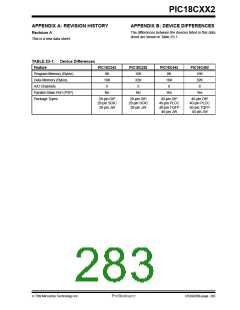
Device Differences ........................................................... 285
Direct Addressing .............................................................. 49
ANDLW ............................................................................ 198
ANDWF ............................................................................ 199
Assembler
MPASM Assembler .................................................. 235
B
Baud Rate Generator ....................................................... 136
BCF .................................................................................. 200
BF .................................................................................... 139
Block Diagrams
Baud Rate Generator ............................................... 136
SSP (SPI Mode) ....................................................... 121
Timer1 ...................................................................... 106
BRG ................................................................................. 136
Brown-out Reset (BOR) ............................................. 24, 181
Timing Diagram ........................................................ 256
BSF .......................... 199, 200, 201, 202, 203, 205, 206, 221
BTFSC ............................................................................. 204
BTFSS ............................................................................. 204
BTG .................................................................................. 205
Bus Collision During a RESTART Condition .................... 148
Bus Collision During a Start Condition ............................. 146
Bus Collision During a Stop Condition ............................. 149
E
Electrical Characteristics ................................................. 241
Errata ................................................................................... 4
F
Firmware Instructions ...................................................... 191
FS0 .................................................................................... 54
FS1 .................................................................................... 54
FS2 .................................................................................... 54
FS3 .................................................................................... 54
G
General Call Address Sequence ..................................... 133
General Call Address Support ......................................... 133
GOTO .............................................................................. 212
C
C ........................................................................................ 54
CALL ................................................................................ 206
Capture (CCP Module) .................................................... 111
Block Diagram .......................................................... 111
CCP Pin Configuration ............................................. 111
CCPR1H:CCPR1L Registers ................................... 111
Changing Between Capture Prescalers ................... 111
I
I/O Ports ............................................................................ 77
2
I C (SSP Module) ............................................................ 128
ACK Pulse ....................................................... 129, 130
Addressing ............................................................... 129
7/99 Microchip Technology Inc.
Preliminary
DS39026B-page 287

 MICROCHIP [ MICROCHIP ]