PIC18CXX2
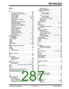
Block Diagram ..........................................................128
Read/Write Bit Information (R/W Bit) ............... 129, 130
Reception .................................................................130
Serial Clock (RC3/SCK/SCL) ...................................130
Slave Mode ..............................................................129
Timing Diagram, Data ..............................................265
Timing Diagram, Start/Stop Bits ...............................264
Transmission ............................................................130
COMF ...................................................................... 208
CPFSEQ .................................................................. 208
CPFSGT .................................................................. 209
CPFSLT ................................................................... 209
DAW ........................................................................ 210
DECF ....................................................................... 210
DECFSNZ ................................................................ 211
DECFSZ .................................................................. 211
GOTO ...................................................................... 212
INCF ........................................................................ 212
INCFSNZ ................................................................. 213
INCFSZ .................................................................... 213
IORLW ..................................................................... 214
IORWF ..................................................................... 214
MOVFP .................................................................... 216
MOVLB .................................................................... 215
MOVLR ............................................................ 215, 216
MOVLW ................................................................... 217
MOVWF ................................................................... 217
MULLW .................................................................... 218
MULWF .................................................................... 218
NEGW ..................................................................... 219
NOP ......................................................................... 219
RETFIE ............................................................ 221, 222
RETLW .................................................................... 222
RETURN .................................................................. 223
RLCF ....................................................................... 223
RLNCF ..................................................................... 224
RRCF ....................................................................... 224
RRNCF .................................................................... 225
SLEEP ..................................................................... 226
SUBLW .................................................................... 227
SUBWF .................................................... 226, 227, 228
SUBWFB ................................................................. 229
SWAPF .................................................................... 230
TABLRD .................................................................. 231
TABLWT .................................................................. 232
TSTFSZ ................................................................... 233
XORLW ................................................................... 233
XORWF ................................................................... 234
Summary Table ....................................................... 194
2
I C Master Mode Reception .............................................139
I C Master Mode Restart Condition .................................138
I C Module
2
2
Acknowledge Sequence timing ................................142
Baud Rate Generator ...............................................136
BRG Block Diagram .................................................136
BRG Reset due to SDA Collision .............................147
BRG Timing .............................................................136
Bus Collision
Acknowledge ....................................................145
Restart Condition .............................................148
Restart Condition Timing (Case1) ....................148
Restart Condition Timing (Case2) ....................148
Start Condition .................................................146
Start Condition Timing ............................. 146, 147
Stop Condition .................................................149
Stop Condition Timing (Case1) ........................149
Stop Condition Timing (Case2) ........................149
Transmit Timing ...............................................145
Bus Collision timing ..................................................145
Clock Arbitration .......................................................144
Clock Arbitration Timing (Master Transmit) ..............144
General Call Address Support .................................133
Master Mode 7-bit Reception timing ........................141
Master Mode Operation ...........................................135
Master Mode Start Condition ...................................137
Master Mode Transmission ......................................139
Master Mode Transmit Sequence ............................135
Multi-master Mode ...................................................145
Repeat Start Condition timing ..................................138
Stop Condition Receive or Transmit timing ..............143
Stop Condition timing ...............................................142
Waveforms for 7-bit Reception ................................130
Waveforms for 7-bit Transmission ...........................130
ID Locations ............................................................. 181, 189
INCF .................................................................................212
INCFSNZ ..........................................................................213
INCFSZ ............................................................................213
In-Circuit Serial Programming (ICSP) ......................181, 189
Indirect Addressing ............................................................49
FSR Register .............................................................48
Instruction Cycle .................................................................37
Instruction Flow/Pipelining .................................................38
Instruction Format ............................................................193
Instruction Set ..................................................................191
ADDLW ....................................................................197
ADDWF ....................................................................197
ADDWFC .................................................................198
ANDLW ....................................................................198
ANDWF ....................................................................199
BCF ..........................................................................200
BSF .................. 199, 200, 201, 202, 203, 205, 206, 221
BTFSC .....................................................................204
BTFSS .....................................................................204
BTG ..........................................................................205
CALL ........................................................................206
CLRF ................................................................207, 225
CLRWDT ..................................................................207
INTCON Register
RBIF Bit ..................................................................... 80
Interrupt Sources ....................................................... 65, 181
A/D Conversion Complete ....................................... 170
Capture Complete (CCP) ......................................... 111
Compare Complete (CCP) ....................................... 112
Interrupt on Change (RB7:RB4 ) ............................... 80
RB0/INT Pin, External ................................................ 75
SSP Receive/Transmit Complete ............................ 117
TMR0 Overflow .......................................................... 95
TMR1 Overflow .................................... 97, 99, 105, 107
TMR2 to PR2 Match ................................................ 103
TMR2 to PR2 Match (PWM) ............................ 102, 115
USART Receive/Transmit Complete ....................... 151
Interrupts, Enable Bits
CCP1 Enable (CCP1IE Bit) ..................................... 111
Interrupts, Flag Bits
A/D Converter Flag (ADIF Bit) ................................. 169
CCP1 Flag (CCP1IF Bit) .................................. 111, 112
Interrupt on Change (RB7:RB4) Flag (RBIF Bit) ........ 80
IORLW ............................................................................. 214
IORWF ............................................................................. 214
K
KeeLoq Evaluation and Programming Tools ................ 238
DS39026B-page 288
Preliminary
7/99 Microchip Technology Inc.
 MICROCHIP [ MICROCHIP ]
