PIC18CXX2
TXREG register transfers the data to the TSR register
(occurs in one TCY), the TXREG register is empty and
flag bit TXIF (PIR1<4>) is set. This interrupt can be
enabled/disabled by setting/clearing enable bit TXIE
( PIE1<4>). Flag bit TXIF will be set regardless of the
state of enable bit TXIE and cannot be cleared in soft-
ware. It will reset only when new data is loaded into the
TXREG register. While flag bit TXIF indicated the sta-
tus of the TXREG register, another bit TRMT
(TXSTA<1>) shows the status of the TSR register. Sta-
tus bit TRMT is a read only bit, which is set when the
TSR register is empty. No interrupt logic is tied to this
bit, so the user has to poll this bit in order to determine
if the TSR register is empty.
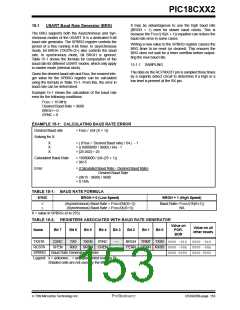
15.2
USART Asynchronous Mode
In this mode, the USART uses standard non-return-to-
zero (NRZ) format (one start bit, eight or nine data bits
and one stop bit). The most common data format is
8-bits. An on-chip dedicated 8-bit baud rate generator
can be used to derive standard baud rate frequencies
from the oscillator. The USART transmits and receives
the LSb first. The USART’s transmitter and receiver are
functionally independent, but use the same data format
and baud rate. The baud rate generator produces a
clock, either x16 or x64 of the bit shift rate, depending
on bit BRGH (TXSTA<2>). Parity is not supported by
the hardware, but can be implemented in software (and
stored as the ninth data bit). Asynchronous mode is
stopped during SLEEP.
Note 1: The TSR register is not mapped in data
memory, so it is not available to the user.
Asynchronous mode is selected by clearing bit SYNC
(TXSTA<4>).
Note 2: Flag bit TXIF is set when enable bit TXEN
is set.
The USART Asynchronous module consists of the fol-
lowing important elements:
Steps to follow when setting up an asynchronous trans-
mission:
• Baud Rate Generator
• Sampling Circuit
1. Initialize the SPBRG register for the appropriate
baud rate. If a high speed baud rate is desired,
set bit BRGH. (Section 15.1)
• Asynchronous Transmitter
• Asynchronous Receiver
2. Enable the asynchronous serial port by clearing
bit SYNC and setting bit SPEN.
15.2.1 USART ASYNCHRONOUS TRANSMITTER
3. If interrupts are desired, set enable bit TXIE.
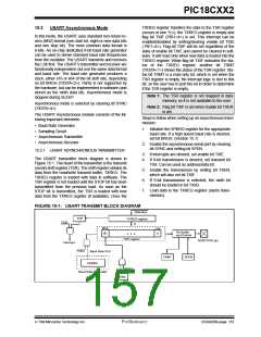
The USART transmitter block diagram is shown in
Figure 15-1. The heart of the transmitter is the transmit
(serial) shift register (TSR). The shift register obtains its
data from the read/write transmit buffer, TXREG. The
TXREG register is loaded with data in software. The
TSR register is not loaded until the STOP bit has been
transmitted from the previous load. As soon as the
STOP bit is transmitted, the TSR is loaded with new
data from the TXREG register (if available). Once the
4. If 9-bit transmission is desired, set transmit bit
TX9. Can be used as address/data bit.
5. Enable the transmission by setting bit TXEN,
which will also set bit TXIF.
6. If 9-bit transmission is selected, the ninth bit
should be loaded in bit TX9D.
7. Load data to the TXREG register (starts trans-
mission).
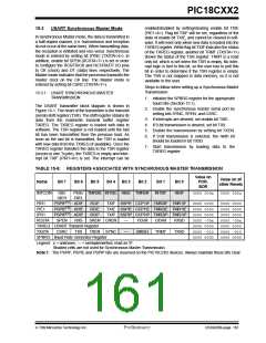
FIGURE 15-1: USART TRANSMIT BLOCK DIAGRAM
Data Bus
TXIF
TXREG register
TXIE
8
MSb
(8)
LSb
0
Pin Buffer
and Control
•
•
•
TSR register
RC6/TX/CK pin
Interrupt
TXEN
Baud Rate CLK
TRMT
SPEN
SPBRG
Baud Rate Generator
TX9
TX9D
7/99 Microchip Technology Inc.
Preliminary
DS39026B-page 157

 MICROCHIP [ MICROCHIP ]