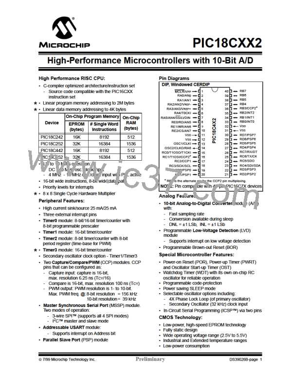
PIC18CXX2
FIGURE 14-21: STOP CONDITION RECEIVE OR TRANSMIT MODE
SCL = 1 for Tbrg, followed by SDA = 1 for Tbrg
after SDA sampled high. P bit (SSPSTAT<4>) is set
Write to SSPCON2
Set PEN
PEN bit (SSPCON2<2>) is cleared by
hardware and the SSPIF bit is set
Falling edge of
9th clock
TBRG
SCL
SDA
ACK
P
TBRG
TBRG
TBRG
SCL brought high after TBRG
SDA asserted low before rising edge of clock
to setup stop condition.
Note: TBRG = one baud rate generator period.
7/99 Microchip Technology Inc.
Preliminary
DS39026B-page 143

 MICROCHIP [ MICROCHIP ]