PIC18F6525/6621/8525/8621
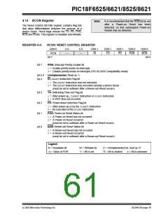
4.14 RCON Register
Note:
It is recommended that the POR bit be set
after Power-on Reset has been
detected, so that subsequent Power-on
Resets may be detected.
a
The Reset Control (RCON) register contains flag bits
that allow differentiation between the sources of a
device Reset. These flags include the TO, PD, POR,
BOR and RI bits. This register is readable and writable.
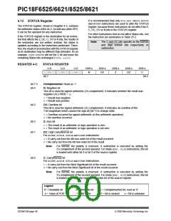
REGISTER 4-4:
RCON: RESET CONTROL REGISTER
R/W-0
IPEN
U-0
—
U-0
—
R/W-1
RI
R/W-1
TO
R/W-1
PD
R/W-0
POR
R/W-0
BOR
bit 7
bit 0
bit 7
IPEN: Interrupt Priority Enable bit
1= Enable priority levels on interrupts
0= Disable priority levels on interrupts (PIC16CXXX Compatibility mode)
bit 6-5 Unimplemented: Read as ‘0’
bit 4
RI: RESETInstruction Flag bit
1= The RESETinstruction was not executed
0= The RESETinstruction was executed causing a device Reset
(must be set in software after a Brown-out Reset occurs)
bit 3
bit 2
bit 1
TO: Watchdog Time-out Flag bit
1= After power-up, CLRWDTinstruction or SLEEPinstruction
0= A WDT time-out occurred
PD: Power-down Detection Flag bit
1= After power-up or by the CLRWDTinstruction
0= By execution of the SLEEPinstruction
POR: Power-on Reset Status bit
1= A Power-on Reset has not occurred
0= A Power-on Reset occurred
(must be set in software after a Power-on Reset occurs)
bit 0
BOR: Brown-out Reset Status bit
1= A Brown-out Reset has not occurred
0= A Brown-out Reset occurred
(must be set in software after a Brown-out Reset occurs)
Legend:
R = Readable bit
-n = Value at POR
W = Writable bit
‘1’ = Bit is set
U = Unimplemented bit, read as ‘0’
‘0’ = Bit is cleared x = Bit is unknown
2005 Microchip Technology Inc.
DS39612B-page 59

 MICROCHIP [ MICROCHIP ]