PIC17C75X
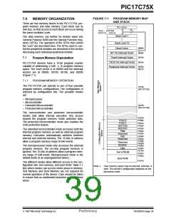
FIGURE 7-1: PROGRAM MEMORY MAP
AND STACK
7.0
MEMORY ORGANIZATION
There are two memory blocks in the PIC17C75X; pro-
gram memory and data memory. Each block has its
own bus, so that access to each block can occur during
the same oscillator cycle.
PC<15:0>
16
CALL, RETURN
RETFIE, RETLW
Stack Level 1
The data memory can further be broken down into
General Purpose RAM and the Special Function Reg-
isters (SFRs). The operation of the SFRs that control
the “core” are described here. The SFRs used to con-
trol the peripheral modules are described in the section
discussing each individual peripheral module.
•
•
•
Stack Level 16
Reset Vector
0000h
INT Pin Interrupt Vector
Timer0 Interrupt Vector
T0CKI Pin Interrupt Vector
Peripheral Interrupt Vector
0008h
0010h
0018h
7.1
Program Memory Organization
PIC17C75X devices have a 16-bit program counter
capable of addressing a 64K x 16 program memory
space. The reset vector is at 0000h and the interrupt
vectors are at 0008h, 0010h, 0018h, and 0020h
(Figure 7-1).
0020h
0021h
7.1.1
PROGRAM MEMORY OPERATION
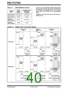
The PIC17C75X can operate in one of four possible
program memory configurations. The configuration is
selected by configuration bits. The possible modes
are:
1FFFh
(PIC17C752)
• Microprocessor
• Microcontroller
3FFFh
(PIC17C756)
• Extended Microcontroller
• Protected Microcontroller
The microcontroller and protected microcontroller
modes only allow internal execution. Any access
beyond the program memory reads unknown data.
The protected microcontroller mode also enables the
code protection feature.
FDFFh
FE00h
FOSC0
FOSC1
WDTPS0
WDTPS1
PM0
Reserved
PM1
Reserved
FE01h
FE02h
FE03h
FE04h
FE05h
FE06h
FE07h
FE08h
FE0Dh
FE0Eh
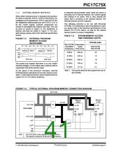
The extended microcontroller mode accesses both the
internal program memory as well as external program
memory. Execution automatically switches between
internal and external memory. The 16-bits of address
allow a program memory range of 64K-words.
Reserved
BODEN
PM2
The microprocessor mode only accesses the external
program memory. The on-chip program memory is
ignored. The 16-bits of address allow a program mem-
ory range of 64K-words. Microprocessor mode is the
default mode of an unprogrammed device.
FE0Fh
FE10h
Test EPROM
FF5Fh
FF60h
Boot ROM
FFFFh
The different modes allow different access to the con-
figuration bits, test memory, and boot ROM. Table 7-1
lists which modes can access which areas in memory.
Test Memory and Boot Memory are not required for
normal operation of the device. Care should be taken
to ensure that no unintended branches occur to these
areas.
Note 1: User memory space may be internal, external, or
both. The memory configuration depends on the
processor mode.
1997 Microchip Technology Inc.
Preliminary
DS30264A-page 39

 MICROCHIP [ MICROCHIP ]