PIC17C4X
The SPEN (RCSTA<7>) bit has to be set in order to
configure RA4 and RA5 as the Serial Communication
Interface.
13.0 UNIVERSAL SYNCHRONOUS
ASYNCHRONOUS RECEIVER
TRANSMITTER (USART)
MODULE
The USART module is a serial I/O module.The USART
can be configured as a full duplex asynchronous sys-
tem that can communicate with peripheral devices such
as CRT terminals and personal computers, or it can be
configured as a half duplex synchronous system that
can communicate with peripheral devices such as A/D
or D/A integrated circuits, Serial EEPROMs etc. The
USART can be configured in the following modes:
The USART module will control the direction of the
RA4/RX/DT and RA5/TX/CK pins, depending on the
states of the USART configuration bits in the RCSTA
and TXSTA registers. The bits that control I/O direction
are:
• SPEN
• TXEN
• SREN
• CREN
• CSRC
• Asynchronous (full duplex)
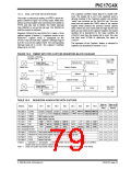
The Transmit Status And Control Register is shown in
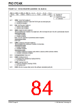
Figure 13-1, while the Receive Status And Control
Register is shown in Figure 13-2.
• Synchronous - Master (half duplex)
• Synchronous - Slave (half duplex)
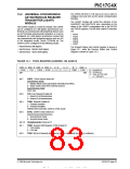
FIGURE 13-1: TXSTA REGISTER (ADDRESS: 15h, BANK 0)
R/W - 0 R/W - 0 R/W - 0 R/W - 0
CSRC TX9 TXEN SYNC
bit7
U - 0
—
U - 0
—
R - 1
TRMT
R/W - x
TX9D
R = Readable bit
W = Writable bit
-n = Value at POR reset
(x = unknown)
bit0
bit 7:
CSRC: Clock Source Select bit
Synchronous mode:
1 = Master Mode (Clock generated internally from BRG)
0 = Slave mode (Clock from external source)
Asynchronous mode:
Don’t care
bit 6:
bit 5:
TX9: 9-bit Transmit Enable bit
1 = Selects 9-bit transmission
0 = Selects 8-bit transmission
TXEN: Transmit Enable bit
1 = Transmit enabled
0 = Transmit disabled
SREN/CREN overrides TXEN in SYNC mode
bit 4:
SYNC: USART mode Select bit
(Synchronous/Asynchronous)
1 = Synchronous mode
0 = Asynchronous mode
bit 3-2: Unimplemented: Read as '0'
bit 1:
TRMT: Transmit Shift Register (TSR) Empty bit
1 = TSR empty
0 = TSR full
bit 0:
TX9D: 9th bit of transmit data (can be used to calculated the parity in software)
1996 Microchip Technology Inc.
DS30412C-page 83
This document was created with FrameMaker 4 0 4

 MICROCHIP [ MICROCHIP ]