PIC17C75X
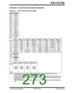
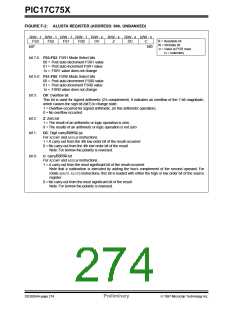
FIGURE F-2: ALUSTA REGISTER (ADDRESS: 04h, UNBANKED)
R/W - 1 R/W - 1 R/W - 1 R/W - 1 R/W - x R/W - x R/W - x R/W - x
R = Readable bit
W = Writable bit
-n = Value at POR reset
(x = unknown)
FS3
FS2
FS1
FS0
OV
Z
DC
C
bit7
bit0
bit 7-6: FS3:FS2: FSR1 Mode Select bits
00 = Post auto-decrement FSR1 value
01 = Post auto-increment FSR1 value
1x = FSR1 value does not change
bit 5-4: FS1:FS0: FSR0 Mode Select bits
00 = Post auto-decrement FSR0 value
01 = Post auto-increment FSR0 value
1x = FSR0 value does not change
bit 3:
OV: Overflow bit
This bit is used for signed arithmetic (2’s complement). It indicates an overflow of the 7-bit magnitude,
which causes the sign bit (bit7) to change state.
1 = Overflow occurred for signed arithmetic, (in this arithmetic operation)
0 = No overflow occurred
bit 2:
bit 1:
Z: Zero bit
1 = The result of an arithmetic or logic operation is zero
0 = The results of an arithmetic or logic operation is not zero
DC: Digit carry/borrow bit
For ADDWFand ADDLWinstructions.
1 = A carry-out from the 4th low order bit of the result occurred
0 = No carry-out from the 4th low order bit of the result
Note: For borrow the polarity is reversed.
bit 0:
C: carry/borrow bit
For ADDWFand ADDLWinstructions.
1 = A carry-out from the most significant bit of the result occurred
Note that a subtraction is executed by adding the two’s complement of the second operand. For
rotate (RRCF, RLCF) instructions, this bit is loaded with either the high or low order bit of the source
register.
0 = No carry-out from the most significant bit of the result
Note: For borrow the polarity is reversed.
DS30264A-page 274
Preliminary
1997 Microchip Technology Inc.

 MICROCHIP [ MICROCHIP ]