PIC17C75X
21.0 PIC17C752/756 DC AND AC CHARACTERISTICS
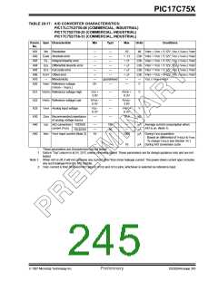
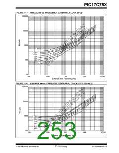
The graphs and tables provided in this section are for design guidance and are not tested nor guaranteed. In some
graphs or tables the data presented is outside specified operating range (e.g. outside specified VDD range). This is for
information only and devices are ensured to operate properly only within the specified range.
The data presented in this section is a statistical summary of data collected on units from different lots over a period of
time. "Typical" represents the mean of the distribution while "max" or "min" represents (mean + 3σ) and (mean - 3σ)
respectively where σ is standard deviation.
TABLE 21-1: PIN CAPACITANCE PER PACKAGE TYPE
Typical Capacitance (pF)
Pin Name
64-pin DIP
68-pin PLCC
64-pin TQFP
All pins, except MCLR, VDD, and VSS
MCLR pin
10
20
10
20
10
20
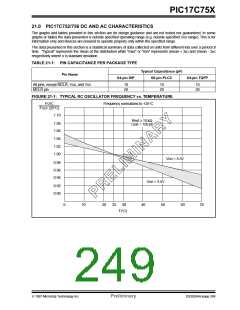
FIGURE 21-1: TYPICAL RC OSCILLATOR FREQUENCY vs. TEMPERATURE
FOSC
Frequency normalized to +25°C
FOSC (25°C)
1.10
Rext ≥ 10 kΩ
Cext = 100 pF
1.08
1.06
1.04
1.02
1.00
VDD = 5.5V
0.98
0.96
0.94
VDD = 3.5V
0.92
0.90
0
10
20
25
30
40
50
60
70
T(°C)
1997 Microchip Technology Inc.
Preliminary
DS30264A-page 249

 MICROCHIP [ MICROCHIP ]