PIC17C75X
2
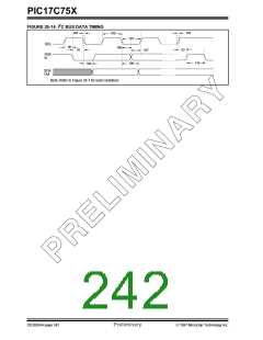
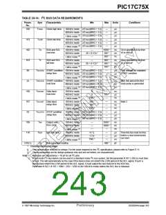
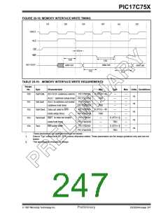
TABLE 20-14: I C BUS DATA REQUIREMENTS
Param.
No.
Sym
Characteristic
Min
Max
Units
Conditions
100
101
102
103
90
THIGH
Clock high time
100 kHz mode 2(TOSC)(BRG + 1) §
—
—
—
µs
µs
µs
400 kHz mode 2(TOSC)(BRG + 1) §
(1)
2(TOSC)(BRG + 1) §
1 MHz mode
TLOW
TR
Clock low time
100 kHz mode 2(TOSC)(BRG + 1) §
—
—
—
µs
µs
µs
400 kHz mode 2(TOSC)(BRG + 1) §
(1)
2(TOSC)(BRG + 1) §
1 MHz mode
100 kHz mode
400 kHz mode
SDA and SCL
rise time
—
20 + 0.1Cb *
—
1000 *
300 *
300 *
ns
ns
ns
Cb is specified to be from
10 to 400 pF
(1)
1 MHz mode
100 kHz mode
400 kHz mode
TF
SDA and SCL
fall time
—
20 + 0.1Cb *
—
300 *
300 *
100 *
ns
ns
ns
Cb is specified to be from
10 to 400 pF
(1)
1 MHz mode
TSU:STA START condition 100 kHz mode 2(TOSC)(BRG + 1) §
—
—
—
µs
µs
µs
Only relevant for repeated
START condition
setup time
400 kHz mode 2(TOSC)(BRG + 1) §
(1)
2(TOSC)(BRG + 1) §
1 MHz mode
91
THD:STA START condition 100 kHz mode 2(TOSC)(BRG + 1) §
—
—
—
µs
µs
µs
After this period the first
clock pulse is generated
hold time
400 kHz mode 2(TOSC)(BRG + 1) §
(1)
2(TOSC)(BRG + 1) §
1 MHz mode
100 kHz mode
400 kHz mode
106
107
92
THD:DAT Data input
hold time
0
0
—
0.9 *
—
ns
µs
ns
(1)
TBD *
1 MHz mode
100 kHz mode
400 kHz mode
TSU:DAT Data input
setup time
250 *
100 *
TBD *
—
—
—
ns
ns
ns
Note 2
(1)
1 MHz mode
TSU:STO STOP condition
setup time
100 kHz mode 2(TOSC)(BRG + 1) §
—
—
—
µs
µs
µs
400 kHz mode 2(TOSC)(BRG + 1) §
(1)
2(TOSC)(BRG + 1) §
1 MHz mode
100 kHz mode
400 kHz mode
109
110
D102 ‡
TAA
TBUF
Cb
Output valid
from clock
—
—
—
3500 *
1000 *
—
ns
ns
ns
(1)
1 MHz mode
100 kHz mode
400 kHz mode
Bus free time
4.7 ‡
1.3 ‡
TBD *
—
—
—
µs
µs
µs
Time the bus must be free
before a new transmission
can start
(1)
1 MHz mode
Bus capacitive loading
—
400 *
pF
*
Characterized but not tested.
2
§
‡
This specification ensured by design. For the value required by the I C specification, please refer to Figure E-11.
These parameters are for design guidance only and are not tested, nor characterized.
2
Note 1: Maximum pin capacitance = 10 pF for all I C pins.
2
2
2: A fast-mode I C-bus device can be used in a standard-mode I C-bus system, but the parameter # 107 ≥ 250 ns must then
be met. This will automatically be the case if the device does not stretch the LOW period of the SCL signal. If such a
device does stretch the LOW period of the SCL signal, it must output the next data bit to the SDA line.
Parameter # 102.+ # 107 = 1000 + 250 = 1250 ns (for 100 kHz-mode) before the SCL line is released.
1997 Microchip Technology Inc.
Preliminary
DS30264A-page 243

 MICROCHIP [ MICROCHIP ]