PIC17C75X
This interrupt can wake the device from SLEEP. The
user, in the interrupt service routine, can clear the inter-
rupt by:
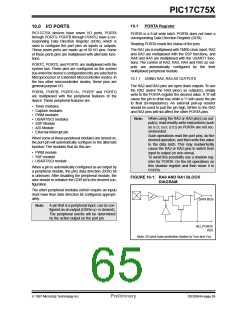
10.2
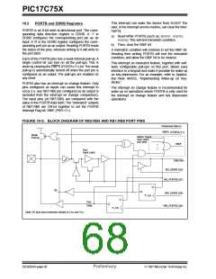
PORTB and DDRB Registers
PORTB is an 8-bit wide bi-directional port. The corre-
sponding data direction register is DDRB. A '1' in
DDRB configures the corresponding port pin as an
input. A '0' in the DDRB register configures the corre-
sponding port pin as an output. Reading PORTB reads
the status of the pins, whereas writing to it will write to
the port latch.
a) Read-Write PORTB (such as; MOVPF PORTB,
PORTB). This will end mismatch condition.
b) Then, clear the RBIF bit.
A mismatch condition will continue to set the RBIF bit.
Reading then writing PORTB will end the mismatch
condition, and allow the RBIF bit to be cleared.
Each of the PORTB pins has a weak internal pull-up. A
single control bit can turn on all the pull-ups. This is
done by clearing the RBPU (PORTA<7>) bit. The weak
pull-up is automatically turned off when the port pin is
configured as an output. The pull-ups are enabled on
any reset.
This interrupt on mismatch feature, together with soft-
ware configurable pull-ups on this port, allows easy
interface to a keypad and make it possible for wake-up
on key-depression. For an example, refer to Applica-
tion Note AN552, “Implementing Wake-up on Key-
stroke.”
PORTB also has an interrupt on change feature. Only
pins configured as inputs can cause this interrupt to
occur (i.e. any RB7:RB0 pin configured as an output is
excluded from the interrupt on change comparison).
The input pins (of RB7:RB0) are compared with the
value in the PORTB data latch.The “mismatch” outputs
of RB7:RB0 are OR’ed together to set the PORTB
Interrupt Flag bit, RBIF (PIR1<7>).
The interrupt on change feature is recommended for
wake-up on operations where PORTB is only used for
the interrupt on change feature and key depression
operations.
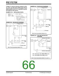
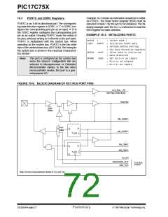
FIGURE 10-5: BLOCK DIAGRAM OF RB5:RB4 AND RB1:RB0 PORT PINS
Peripheral Data in
RBPU
(PORTA<7>)
Weak
Pull-Up
Match Signal
from other
port pins
RBIF
Port
Input Latch
Data Bus
RD_DDRB (Q2)
RD_PORTB (Q2)
D
OE
Q
WR_DDRB (Q4)
WR_PORTB (Q4)
CK
D
Port
Q
Data
CK
Note: I/O pins have protection diodes to VDD and VSS.
DS30264A-page 68
Preliminary
1997 Microchip Technology Inc.

 MICROCHIP [ MICROCHIP ]