PIC17C75X
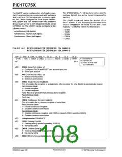
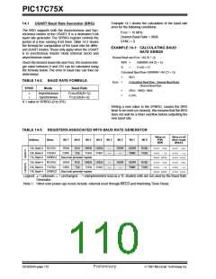
Example 14-1 shows the calculation of the baud rate
error for the following conditions:
14.1
USART Baud Rate Generator (BRG)
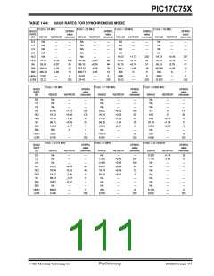
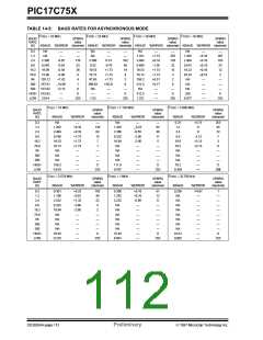
The BRG supports both the Asynchronous and Syn-
chronous modes of the USART. It is a dedicated 8-bit
baud rate generator. The SPBRG register controls the
period of a free running 8-bit timer. Table 14-2 shows
the formula for computation of the baud rate for differ-
ent USART modes.These only apply when the USART
is in synchronous master mode (internal clock) and
asynchronous mode.
FOSC = 16 MHz
Desired Baud Rate = 9600
SYNC = 0
EXAMPLE 14-1: CALCULATING BAUD
RATE ERROR
Desired Baud rate=Fosc / (64 (X + 1))
9600
X
=
=
16000000 /(64 (X + 1))
25.042 = 25
Given the desired baud rate and Fosc, the nearest inte-
ger value between 0 and 255 can be calculated using
the formula below. The error in baud rate can then be
determined.
Calculated Baud Rate=16000000 / (64 (25 + 1))
=
=
9615
TABLE 14-2: BAUD RATE FORMULA
Error
(Calculated Baud Rate - Desired Baud Rate)
Desired Baud Rate
SYNC
Mode
Baud Rate
=
=
(9615 - 9600) / 9600
0.16%
0
1
Asynchronous
Synchronous
FOSC/(64(X+1))
FOSC/(4(X+1))
X = value in SPBRG (0 to 255)
Writing a new value to the SPBRG, causes the BRG
timer to be reset (or cleared), this ensures that the BRG
does not wait for a timer overflow before outputting the
new baud rate.
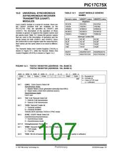
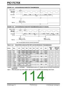
TABLE 14-3: REGISTERS ASSOCIATED WITH BAUD RATE GENERATOR
Value on
POR,
BOR
Value on all
other resets
(Note1)
Address
Name
Bit 7
Bit 6
Bit 5
Bit 4
Bit 3
Bit 2
Bit 1
Bit 0
13h, Bank 0
RCSTA1
SPEN
CSRC
RX9
TX9
SREN
TXEN
CREN
SYNC
—
—
FERR
—
OERR
TRMT
RX9D
TX9D
0000 -00x
0000 -00u
15h, Bank 0
17h, Bank 0
TXSTA1
0000 --1x
xxxx xxxx
0000 --1u
uuuu uuuu
SPBRG1
Baud rate generator register
13h, Bank 4
RCSTA2
SPEN
CSRC
RX9
TX9
SREN
TXEN
CREN
SYNC
—
—
FERR
—
OERR
TRMT
RX9D
TX9D
0000 -00x
0000 -00u
15h, Bank 4
17h, Bank 4
TXSTA2
0000 --1x
xxxx xxxx
0000 --1u
uuuu uuuu
SPBRG2
Baud rate generator register
Legend: x= unknown, u= unchanged, -= unimplemented read as a '0', shaded cells are not used by the Baud Rate
Generator.
Note 1: Other (non power-up) resets include: external reset through MCLR and Watchdog Timer Reset.
DS30264A-page 110
Preliminary
1997 Microchip Technology Inc.

 MICROCHIP [ MICROCHIP ]