PIC16F913/914/916/917/946
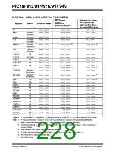
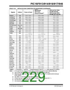
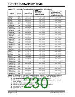
TABLE 16-4: INITIALIZATION CONDITION FOR REGISTERS (CONTINUED)
• Wake-up from Sleep
through interrupt
• MCLR Reset
• WDT Reset
• Brown-out Reset(1)
Register
Address
Power-on Reset
• Wake-up from Sleep
through WDT time-out
LVDCON
109h
10Ch
10Dh
10Eh
10Fh
110h
111h
112h
113h
114h
115h
116h
117h
118h
119h
11Ah
11Bh
11Ch
11Dh
11Eh
185h
187h
188h
189h
190h
191h
192h
193h
194h
195h
196h
197h
198h
199h
--00 -100
0000 0000
0000 0000
--00 0000
---0 0000
xxxx xxxx
xxxx xxxx
xxxx xxxx
xxxx xxxx
xxxx xxxx
xxxx xxxx
xxxx xxxx
xxxx xxxx
xxxx xxxx
xxxx xxxx
xxxx xxxx
xxxx xxxx
0000 0000
0000 0000
0000 0000
1111 1111
--11 1111
xxxx xxxx
--xx xxxx
xxxx xxxx
xxxx xxxx
---- --xx
xxxx xxxx
xxxx xxxx
---- --xx
xxxx xxxx
xxxx xxxx
---- --xx
xxxx xxxx
--00 -100
0000 0000
0000 0000
0000 0000
0000 0000
uuuu uuuu
uuuu uuuu
uuuu uuuu
uuuu uuuu
uuuu uuuu
uuuu uuuu
uuuu uuuu
uuuu uuuu
uuuu uuuu
uuuu uuuu
uuuu uuuu
uuuu uuuu
uuuu uuuu
uuuu uuuu
uuuu uuuu
1111 1111
--11 1111
0000 0000
--00 0000
uuuu uuuu
uuuu uuuu
---- --uu
uuuu uuuu
uuuu uuuu
---- --uu
uuuu uuuu
uuuu uuuu
---- --uu
uuuu uuuu
--uu -uuu
uuuu uuuu
uuuu uuuu
uuuu uuuu
uuuu uuuu
uuuu uuuu
uuuu uuuu
uuuu uuuu
uuuu uuuu
uuuu uuuu
uuuu uuuu
uuuu uuuu
uuuu uuuu
uuuu uuuu
uuuu uuuu
uuuu uuuu
uuuu uuuu
uuuu uuuu
uuuu uuuu
uuuu uuuu
uuuu uuuu
--uu uuuu
uuuu uuuu
--uu uuuu
uuuu uuuu
uuuu uuuu
---- --uu
uuuu uuuu
uuuu uuuu
---- --uu
uuuu uuuu
uuuu uuuu
---- --uu
uuuu uuuu
EEDATL
EEADRL
EEDATH
EEADRH
LCDDATA0
LCDDATA1
LCDDATA2(6)
LCDDATA3
LCDDATA4
LCDDATA5(6)
LCDDATA6
LCDDATA7
LCDDATA8(6)
LCDDATA9
LCDDATA10
LCDDATA11(6)
LCDSE0
LCDSE1
LCDSE2(6)
TRISF(7)
TRISG(7)
PORTF(7)
PORTG(7)
LCDDATA12(7)
LCDDATA13(7)
LCDDATA14(7)
LCDDATA15(7)
LCDDATA16(7)
LCDDATA17(7)
LCDDATA18(7)
LCDDATA19(7)
LCDDATA20(7)
LCDDATA21(7)
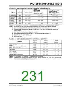
Legend: u= unchanged, x= unknown, - = unimplemented bit, reads as ‘0’, q= value depends on condition.
Note 1: If VDD goes too low, Power-on Reset will be activated and registers will be affected differently.
2: One or more bits in INTCON and/or PIR1 will be affected (to cause wake-up).
3: When the wake-up is due to an interrupt and the GIE bit is set, the PC is loaded with the interrupt
vector (0004h).
4: See Table 16-5 for Reset value for specific condition.
5: If Reset was due to brown-out, then bit 0 = 0. All other Resets will cause bit 0 = u.
6: PIC16F914/917 and PIC16F946 only.
7: PIC16F946 only.
DS41250F-page 228
© 2007 Microchip Technology Inc.

 MICROCHIP [ MICROCHIP ]