PIC16F913/914/916/917/946
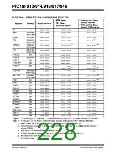
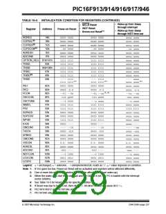
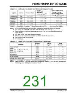
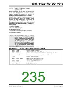
TABLE 16-4: INITIALIZATION CONDITION FOR REGISTERS (CONTINUED)
• Wake-up from Sleep
through interrupt
• MCLR Reset
• WDT Reset
• Brown-out Reset(1)
Register
Address
Power-on Reset
• Wake-up from Sleep
through WDT time-out
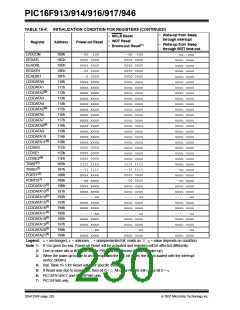
LCDDATA22(7)
LCDDATA23(7)
LCDSE3(7)
LCDSE4(7)
LCDSE5(7)
EECON1
19Ah
19Bh
19Ch
19Dh
19Eh
18Ch
xxxx xxxx
---- --xx
0000 0000
0000 0000
---- --00
x--- x000
uuuu uuuu
---- --uu
uuuu uuuu
uuuu uuuu
---- --uu
u--- q000
uuuu uuuu
---- --uu
uuuu uuuu
uuuu uuuu
---- --uu
u--- uuuu
Legend: u= unchanged, x= unknown, - = unimplemented bit, reads as ‘0’, q= value depends on condition.
Note 1: If VDD goes too low, Power-on Reset will be activated and registers will be affected differently.
2: One or more bits in INTCON and/or PIR1 will be affected (to cause wake-up).
3: When the wake-up is due to an interrupt and the GIE bit is set, the PC is loaded with the interrupt
vector (0004h).
4: See Table 16-5 for Reset value for specific condition.
5: If Reset was due to brown-out, then bit 0 = 0. All other Resets will cause bit 0 = u.
6: PIC16F914/917 and PIC16F946 only.
7: PIC16F946 only.
TABLE 16-5: INITIALIZATION CONDITION FOR SPECIAL REGISTERS
Program
Counter
STATUS
Register
PCON
Register
Condition
Power-on Reset
0000h
0000h
0001 1xxx
000u uuuu
---1 --0x
---u --uu
MCLR Reset during normal operation
MCLR Reset during Sleep
WDT Reset
0000h
0000h
0001 0uuu
0000 uuuu
uuu0 0uuu
0001 1uuu
uuu1 0uuu
---u --uu
---u --uu
---u --uu
---1 --10
---u --uu
WDT Wake-up
PC + 1
Brown-out Reset
0000h
PC + 1(1)
Interrupt Wake-up from Sleep
Legend: u= unchanged, x= unknown, -= unimplemented bit, reads as ‘0’.
Note 1: When the wake-up is due to an interrupt and Global Interrupt Enable bit, GIE, is set, the PC is loaded with
the interrupt vector (0004h) after execution of PC + 1.
© 2007 Microchip Technology Inc.
DS41250F-page 229

 MICROCHIP [ MICROCHIP ]