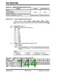
PIC16F87/88
interrupt enable bit must be set (enabled). Wake-up
occurs regardless of the state of the GIE bit. If the GIE
bit is clear (disabled), the device continues execution at
the instruction after the SLEEPinstruction. If the GIE bit
is set (enabled), the device executes the instruction
after the SLEEP instruction and then branches to the
interrupt address (0004h). In cases where the execu-
tion of the instruction following SLEEPis not desirable,
the user should have a NOPafter the SLEEPinstruction.
15.13.1 WAKE-UP FROM SLEEP
The device can wake-up from SLEEP through one of
the following events:
1. External RESET input on MCLR pin.
2. Watchdog Timer wake-up (if WDT was enabled).
3. Interrupt from INT pin, RB port change or a
peripheral interrupt.
External MCLR Reset will cause a device RESET. All
other events are considered a continuation of program
execution and cause a “wake-up”. The TO and PD bits
in the STATUS register can be used to determine the
cause of the device RESET. The PD bit, which is set on
power-up, is cleared when SLEEP is invoked. The TO
bit is cleared if a WDT time-out occurred and caused
wake-up.
15.13.2 WAKE-UP USING INTERRUPTS
When global interrupts are disabled (GIE cleared) and
any interrupt source has both its interrupt enable bit
and interrupt flag bit set, one of the following will occur:
• If the interrupt occurs before the execution of a
SLEEPinstruction, the SLEEPinstruction will com-
plete as a NOP. Therefore, the WDT and WDT
prescaler and postscaler (if enabled) will not be
cleared, the TO bit will not be set and the PD bit
will not be cleared.
The following peripheral interrupts can wake the device
from SLEEP:
1. TMR1 interrupt. Timer1 must be operating as an
asynchronous counter.
• If the interrupt occurs during or after the
execution of a SLEEPinstruction, the device will
immediately wake-up from SLEEP. The SLEEP
instruction will be completely executed before the
wake-up. Therefore, the WDT and WDT prescaler
and postscaler (if enabled) will be cleared, the TO
bit will be set and the PD bit will be cleared.
2. CCP Capture mode interrupt.
3. Special event trigger (Timer1 in Asynchronous
mode using an external clock).
4. SSP (START/STOP) bit detect interrupt.
5. SSP transmit or receive in Slave mode (SPI/I2C).
6. A/D conversion (when A/D clock source is RC).
7. EEPROM write operation completion.
Even if the flag bits were checked before executing a
SLEEP instruction, it may be possible for flag bits to
become set before the SLEEPinstruction completes. To
determine whether a SLEEPinstruction executed, test
the PD bit. If the PD bit is set, the SLEEP instruction
was executed as a NOP.
8. Comparator output changes state.
9. USART RX or TX (Synchronous Slave mode).
Other peripherals cannot generate interrupts, since
during SLEEP, no on-chip clocks are present.
When the SLEEPinstruction is being executed, the next
instruction (PC + 1) is pre-fetched. For the device to
wake-up through an interrupt event, the corresponding
To ensure that the WDT is cleared, a CLRWDTinstruction
should be executed before a SLEEPinstruction.
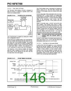
FIGURE 15-12:
WAKE-UP FROM SLEEP THROUGH INTERRUPT(1)
Q1 Q2 Q3 Q4 Q1 Q2 Q3 Q4 Q1
Q1 Q2 Q3 Q4 Q1 Q2 Q3 Q4 Q1 Q2 Q3 Q4 Q1 Q2 Q3 Q4
OSC1
(2)
TOST
CLKO(4)
INT pin
INTF Flag
Interrupt Latency
(INTCON<1>)
(Note 2)
GIE bit(3)
(INTCON<7>)
Processor in
SLEEP
INSTRUCTION FLOW
PC
PC
PC+1
PC+2
PC+2
PC + 2
0004h
0005h
Instruction
Fetched
Inst(0004h)
Inst(PC + 1)
Inst(PC + 2)
Inst(0005h)
Inst(PC) = SLEEP
Instruction
Executed
Dummy Cycle
Dummy Cycle
SLEEP
Inst(PC + 1)
Inst(PC - 1)
Inst(0004h)
Note 1: XT, HS or LP Oscillator mode assumed.
2: TOST = 1024 TOSC (drawing not to scale). This delay will not be there for RC Osc mode.
3: GIE = 1assumed. In this case, after wake-up, the processor jumps to the interrupt routine.
If GIE = 0, execution will continue in-line.
4: CLKO is not available in these Osc modes, but shown here for timing reference.
DS30487B-page 146
Preliminary
2003 Microchip Technology Inc.

 MICROCHIP [ MICROCHIP ]