PIC12F508/509/16F505
4.3.2
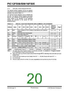
SPECIAL FUNCTION REGISTERS
The Special Function Registers (SFRs) are registers
used by the CPU and peripheral functions to control the
operation of the device (Table 4-1).
The Special Function Registers can be classified into
two sets. The Special Function Registers associated
with the “core” functions are described in this section.
Those related to the operation of the peripheral
features are described in the section for each
peripheral feature.
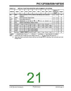
TABLE 4-1:
Address
SPECIAL FUNCTION REGISTER (SFR) SUMMARY (PIC12F508/509)
Value on
Power-On
Reset(2)
Name
INDF
TMR0
Bit 7
Bit 6 Bit 5 Bit 4
Bit 3
Bit 2
Bit 1 Bit 0
Page #
00h
Uses Contents of FSR to Address Data Memory (not a physical
register)
xxxx xxxx
26
01h
8-bit Real-Time Clock/Counter
xxxx xxxx
1111 1111
0-01 1xxx(3)
33
25
20
02h(1)
PCL
Low-order 8 bits of PC
03h
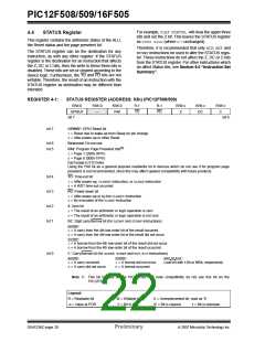
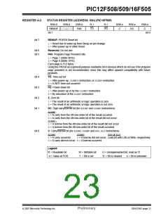
STATUS
GPWU
F
—
PA0(5)
TO
PD
Z
DC
C
04h
04h(4)
05h
06h
N/A
FSR
Indirect Data Memory Address Pointer
Indirect Data Memory Address Pointer
CAL6 CAL5 CAL4 CAL3 CAL2
111x xxxx
110x xxxx
1111 111-
--xx xxxx
--11 1111
1111 1111
26
26
24
29
29
22
FSR
OSCCAL
GPIO
CAL1 CAL0
—
—
—
—
—
GP5
I/O Control Register
PSA
GP4
GP3
GP2
GP1 GP0
TRISGPIO
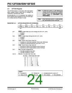
OPTION
N/A
GPWU GPPU TOCS TOSE
PS2
PS1 PS0
Legend: – = unimplemented, read as ‘0’, x= unknown, u= unchanged, q= value depends on condition.
Note 1: The upper byte of the Program Counter is not directly accessible. See Section 4.7 “Program Counter”
for an explanation of how to access these bits.
2: Other (non Power-up) Resets include external Reset through MCLR, Watchdog Timer and wake-up on pin
change Reset.
3: If Reset was due to wake-up on pin change, then bit 7 = 1. All other Resets will cause bit 7 = 0.
4: PIC12F509 only.
5: This bit is used on the PIC12F509. For code compatibility do not use this bit on the PIC12F508.
DS41236C-page 18
Preliminary
© 2007 Microchip Technology Inc.

 MICROCHIP [ MICROCHIP ]