PIC16C55X(A)
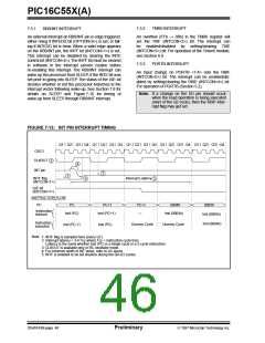
For external interrupt events, such as the INT pin or
PORTB change interrupt, the interrupt latency will be
three or four instruction cycles. The exact latency
depends when the interrupt event occurs (Figure 7-13).
The latency is the same for one or two cycle
instructions. Once in the interrupt service routine the
source(s) of the interrupt can be determined by polling
the interrupt flag bits. The interrupt flag bit(s) must be
cleared in software before re-enabling interrupts to
avoid multiple interrupt requests. Individual interrupt
flag bits are set regardless of the status of their
corresponding mask bit or the GIE bit.
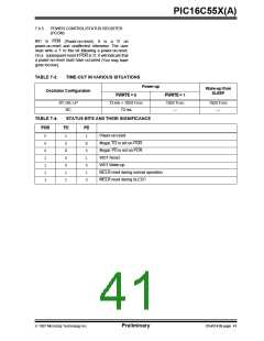
7.5
Interrupts
The PIC16C55X(A) has 3 sources of interrupt:
• External interrupt RB0/INT
• TMR0 overflow interrupt
• PortB change interrupts (pins RB7:RB4)
The interrupt control register (INTCON) records
individual interrupt requests in flag bits. It also has
individual and global interrupt enable bits.
A global interrupt enable bit, GIE (INTCON<7>)
enables (if set) all un-masked interrupts or disables (if
cleared) all interrupts. Individual interrupts can be
disabled through their corresponding enable bits in
INTCON register. GIE is cleared on reset.
Note 1: Individual interrupt flag bits are set
regardless of the status of their
corresponding mask bit or the GIE bit.
2: When an instruction that clears the GIE
bit is executed, any interrupts that were
pending for execution in the next cycle
are ignored. The CPU will execute a
NOP in the cycle immediately following
the instruction which clears the GIE bit.
The interrupts which were ignored are
still pending to be serviced when the GIE
bit is set again.
The “return from interrupt” instruction, RETFIE, exits
the interrupt routine as well as sets the GIE bit, which
re-enables RB0/INT interrupts.
The INT pin interrupt, the RB port change interrupt and
the TMR0 overflow interrupt flags are contained in the
INTCON register.
When an interrupt is responded to, the GIE is cleared
to disable any further interrupt, the return address is
pushed into the stack and the PC is loaded with 0004h.
Once in the interrupt service routine the source(s) of
the interrupt can be determined by polling the interrupt
flag bits.The interrupt flag bit(s) must be cleared in soft-
ware before re-enabling interrupts to avoid RB0/INT
recursive interrupts.
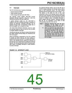
FIGURE 7-12: INTERRUPT LOGIC
Wake-up
(If in SLEEP mode)
T0IF
T0IE
INTF
INTE
Interrupt
to CPU
RBIF
RBIE
GIE
1997 Microchip Technology Inc.
Preliminary
DS40143B-page 45

 MICROCHIP [ MICROCHIP ]