PIC16F716
9.10.1
INT INTERRUPT
9.11 Context Saving During Interrupts
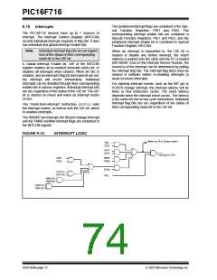
External interrupt on RB0/INT pin is edge triggered,
either rising if bit INTEDG of the OPTION register is set,
or falling if the INTEDG bit is clear. When a valid edge
appears on the RB0/INT pin, flag bit INTF of the
INTCON register is set. This interrupt can be disabled
by clearing enable bit INTE of the INTCON register.
Flag bit INTF must be cleared in software in the Inter-
rupt Service Routine before re-enabling this interrupt.
The INT interrupt can wake-up the processor from
Sleep, if bit INTE was set prior to going into Sleep. The
status of global interrupt enable bit GIE decides
whether or not the processor branches to the interrupt
vector following wake-up. See Section 9.13
“Power-down Mode (Sleep)” for details on Sleep
mode.
During an interrupt, only the return PC value is saved
on the stack. Typically, users may wish to save key
registers during an interrupt, (i.e., W register and
STATUS register). This will have to be implemented in
firmware.
Example 9-1 stores and restores the W, STATUS,
PCLATH and FSR registers. Context storage registers,
W_TEMP, STATUS_TEMP, PCLATH_TEMP and
FSR_TEMP, must be defined in Common RAM which
are those addresses between 70h-7Fh in Bank 0 and
between F0h-FFh in Bank 1.
The example:
a) Stores the W register.
b) Stores the STATUS register in Bank 0.
c) Stores the PCLATH register.
d) Stores the FSR register.
9.10.2
TMR0 INTERRUPT
An overflow (FFh → 00h) in the TMR0 register will set
flag bit T0IF of the INTCON register. The interrupt can
be enabled/disabled by setting/clearing enable bit
T0IE of the INTCON register. (Section 4.0 “Timer0
Module”).
e) Executes the Interrupt Service Routine code
(User-generated).
f) Restores all saved registers in reverse order
from which they were stored.
9.10.3
PORTB INTCON CHANGE
An input change on PORTB<7:4> sets flag bit RBIF of
the INTCON register. The interrupt can be
enabled/disabled by setting/clearing enable bit RBIE of
the INTCON register. (Section 3.2 “PORTB and the
TRISB Register”).
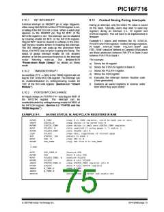
EXAMPLE 9-1:
SAVING STATUS, W, AND PCLATH REGISTERS IN RAM
MOVWF
SWAPF
MOVWF
MOVF
MOVWF
CLRF
BCF
MOVF
MOVWF
:
W_TEMP
;Copy W to TEMP register, could be bank one or zero
STATUS,W
STATUS_TEMP
PCLATH, W
PCLATH_TEMP
PCLATH
STATUS, IRP
FSR, W
FSR_TEMP
;Swap status to be saved into W
;Save status to bank zero STATUS_TEMP register
;Only required if using pages 1, 2 and/or 3
;Save PCLATH into W
;Page zero, regardless of current page
;Return to Bank 0
;Copy FSR to W
;Copy FSR from W to FSR_TEMP
:(ISR)
:
MOVF
MOVWF
MOVF
MOVWF
SWAPF
MOVWF
SWAPF
SWAPF
RETFIE
FSR_TEMP,W
FSR
PCLATH_TEMP, W
PCLATH
STATUS_TEMP,W
STATUS
W_TEMP,F
W_TEMP,W
;Restore FSR
;Move W into FSR
;Restore PCLATH
;Move W into PCLATH
;Swap STATUS_TEMP register into W
;Move W into STATUS register
;Swap W_TEMP
;Swap W_TEMP into W
;Return from interrupt and enable GIE
© 2007 Microchip Technology Inc.
DS41206B-page 73

 MICROCHIP [ MICROCHIP ]