PIC16F716
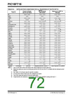
TABLE 9-6:
Register
INITIALIZATION CONDITIONS FOR ALL REGISTERS OF THE PIC16F716
Power-on Reset,
Brown-out Reset
MCLR Resets
WDT Reset
Wake-up via WDT or
Interrupt
W
xxxx xxxx
N/A
uuuu uuuu
N/A
uuuu uuuu
N/A
INDF
TMR0
xxxx xxxx
0000h
uuuu uuuu
0000h
uuuu uuuu
PC + 1(2)
PCL
STATUS
0001 1xxx
xxxx xxxx
--xx 0000
xxxx xxxx
---0 0000
0000 -00x
-0-- -000
xxxx xxxx
xxxx xxxx
--00 0000
0000 0000
-000 0000
xxxx xxxx
xxxx xxxx
0000 0000
0000 0000
00-0 0000
xxxx xxxx
0000 0000
1111 1111
--11 1111
1111 1111
-0-- -000
---- --qq
1111 1111
---- -000
000q quuu(3)
uuuu uuuu
--xx 0000
uuuu uuuu
---0 0000
0000 -00u
-0-- -000
uuuu uuuu
uuuu uuuu
--uu uuuu
0000 0000
-000 0000
uuuu uuuu
uuuu uuuu
0000 0000
0000 0000
00-0 0000
uuuu uuuu
0000 0000
1111 1111
--11 1111
1111 1111
-0-- -000
---- --uu
1111 1111
---- -000
uuuq quuu(3)
uuuu uuuu
--uu uuuu
uuuu uuuu
---u uuuu
uuuu -uuu(1)
-u-- -uuu(1)
uuuu uuuu
uuuu uuuu
--uu uuuu
uuuu uuuu
-uuu uuuu
uuuu uuuu
uuuu uuuu
uuuu uuuu
uuuu uuuu
u-uu uuuu
uuuu uuuu
uuuu uuuu
uuuu uuuu
--uu uuuu
uuuu uuuu
-u-- -uuu
---- --uu
uuuu uuuu
---- -uuu
FSR
PORTA(4), (5), (6)
PORTB(4), (5)
PCLATH
INTCON
PIR1
TMR1L
TMR1H
T1CON
TMR2
T2CON
CCPR1L
CCPR1H
CCP1CON
PWM1CON
ECCPAS
ADRES
ADCON0
OPTION_REG
TRISA
TRISB
PIE1
PCON
PR2
ADCON1
Legend: u = unchanged, x = unknown, -= unimplemented bit, read as ‘0’, q= value depends on condition
Note 1: One or more bits in INTCON and/or PIR1 will be affected (to cause wake-up).
2: When the wake-up is due to an interrupt and the GIE bit is set, the PC is loaded with the interrupt vector
(0004h).
3: See Table 9-5 for Reset value for specific condition.
4: On any device Reset, these pins are configured as inputs.
5: This is the value that will be in the port output latch.
6: Output latches are unknown or unchanged. Analog inputs default to analog and read ‘0’.
DS41206B-page 70
© 2007 Microchip Technology Inc.

 MICROCHIP [ MICROCHIP ]