PIC16F716
2.2.2.5
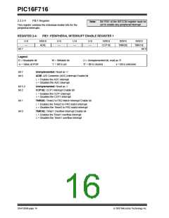
PIR1 Register
Note:
Interrupt flag bits get set when an interrupt
condition occurs, regardless of the state of
its corresponding enable bit or the global
enable bit, GIE of the INTCON register.
User software should ensure the
appropriate interrupt flag bits are clear
prior to enabling an interrupt.
This register contains the individual flag bits for the
peripheral interrupts.
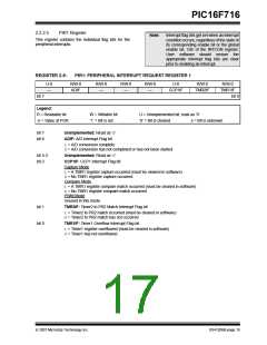
REGISTER 2-5:
PIR1: PERIPHERAL INTERRUPT REQUEST REGISTER 1
U-0
—
R/W-0
ADIF
R/W-0
—
R/W-0
—
R/W-0
—
U-0
R/W-0
R/W-0
CCP1IF
TMR2IF
TMR1IF
bit 7
bit 0
Legend:
R = Readable bit
-n = Value at POR
W = Writable bit
‘1’ = Bit is set
U = Unimplemented bit, read as ‘0’
‘0’ = Bit is cleared x = Bit is unknown
bit 7
bit 6
Unimplemented: Read as ‘0’
ADIF: A/D Interrupt Flag bit
1= A/D conversion complete
0= A/D conversion has not completed or has not been started
bit 5-3
bit 2
Unimplemented: Read as ‘0’
CCP1IF: CCP1 Interrupt Flag bit
Capture Mode
1= A TMR1 register capture occurred (must be cleared in software)
0= No TMR1 register capture occurred
Compare Mode
1= A TMR1 register compare match occurred (must be cleared in software)
0= No TMR1 register compare match occurred
PWM Mode
Unused in this mode
bit 1
bit 0
TMR2IF: Timer2 to PR2 Match Interrupt Flag bit
1= Timer2 to PR2 match occurred (must be cleared in software)
0= Timer2 to PR2 match has not occurred
TMR1IF: Timer1 Overflow Interrupt Flag bit
1= Timer1 register overflowed (must be cleared in software)
0= Timer1 has not overflowed
© 2007 Microchip Technology Inc.
DS41206B-page 15

 MICROCHIP [ MICROCHIP ]