PIC16F/LF1946/47
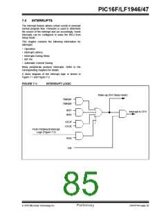
7.1
Operation
7.2
Interrupt Latency
Interrupts are disabled upon any device Reset. They
are enabled by setting the following bits:
Interrupt latency is defined as the time from when the
interrupt event occurs to the time code execution at the
interrupt vector begins. The latency for synchronous
interrupts is 3 or 4 instruction cycles. For asynchronous
interrupts, the latency is 3 to 5 instruction cycles,
depending on when the interrupt occurs. See Figure 7-3
and Figure 7-4 for more details.
• GIE bit of the INTCON register
• Interrupt Enable bit(s) for the specific interrupt
event(s)
• PEIE bit of the INTCON register (if the Interrupt
Enable bit of the interrupt event is contained in the
PIE1, PIE2 and PIE3 registers)
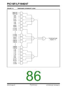
The INTCON, PIR1, PIR2 and PIR3 registers record
individual interrupts via interrupt flag bits. Interrupt flag
bits will be set, regardless of the status of the GIE, PEIE
and individual interrupt enable bits.
The following events happen when an interrupt event
occurs while the GIE bit is set:
• Current prefetched instruction is flushed
• GIE bit is cleared
• Current Program Counter (PC) is pushed onto the
stack
• Critical registers are automatically saved to the
shadow registers (See Section 7.5 “Automatic
Context Saving”)
• PC is loaded with the interrupt vector 0004h
The firmware within the Interrupt Service Routine (ISR)
should determine the source of the interrupt by polling
the interrupt flag bits. The interrupt flag bits must be
cleared before exiting the ISR to avoid repeated
interrupts. Because the GIE bit is cleared, any interrupt
that occurs while executing the ISR will be recorded
through its interrupt flag, but will not cause the
processor to redirect to the interrupt vector.
The RETFIE instruction exits the ISR by popping the
previous address from the stack, restoring the saved
context from the shadow registers and setting the GIE
bit.
For additional information on a specific interrupt’s
operation, refer to its peripheral chapter.
Note 1: Individual interrupt flag bits are set,
regardless of the state of any other
enable bits.
2: All interrupts will be ignored while the GIE
bit is cleared. Any interrupt occurring
while the GIE bit is clear will be serviced
when the GIE bit is set again.
2010 Microchip Technology Inc.
Preliminary
DS41414A-page 85

 MICROCHIP [ MICROCHIP ]