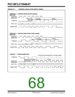
PIC16F/LF1946/47
5.4.1
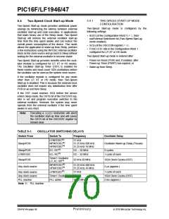
TWO-SPEED START-UP MODE
CONFIGURATION
5.4
Two-Speed Clock Start-up Mode
Two-Speed Start-up mode provides additional power
savings by minimizing the latency between external
oscillator start-up and code execution. In applications
that make heavy use of the Sleep mode, Two-Speed
Start-up will remove the external oscillator start-up
time from the time spent awake and can reduce the
overall power consumption of the device. This mode
allows the application to wake-up from Sleep, perform
a few instructions using the INTOSC internal oscillator
block as the clock source and go back to Sleep without
waiting for the external oscillator to become stable.
Two-Speed Start-up mode is configured by the
following settings:
• IESO (of the Configuration Word 1) = 1; Inter-
nal/External Switchover bit (Two-Speed Start-up
mode enabled).
• SCS (of the OSCCON register) = 00.
• FOSC<2:0> bits in the Configuration Word 1
configured for LP, XT or HS mode.
Two-Speed Start-up mode is entered after:
• Power-on Reset (POR) and, if enabled, after
Power-up Timer (PWRT) has expired, or
Two-Speed Start-up provides benefits when the oscil-
lator module is configured for LP, XT or HS modes.
The Oscillator Start-up Timer (OST) is enabled for
these modes and must count 1024 oscillations before
the oscillator can be used as the system clock source.
• Wake-up from Sleep.
If the oscillator module is configured for any mode
other than LP, XT or HS mode, then Two-Speed
Start-up is disabled. This is because the external clock
oscillator does not require any stabilization time after
POR or an exit from Sleep.
If the OST count reaches 1024 before the device
enters Sleep mode, the OSTS bit of the OSCSTAT reg-
ister is set and program execution switches to the
external oscillator. However, the system may never
operate from the external oscillator if the time spent
awake is very short.
Note:
Executing a SLEEP instruction will abort
the oscillator start-up time and will cause
the OSTS bit of the OSCSTAT register to
remain clear.
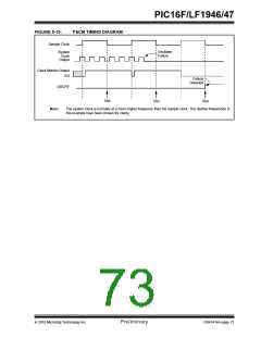
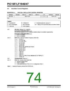
TABLE 5-1:
Switch From
OSCILLATOR SWITCHING DELAYS
Switch To
Frequency
Oscillator Delay
LFINTOSC(1)
MFINTOSC(1)
HFINTOSC(1)
31 kHz
31.25 kHz-500 kHz
31.25 kHz-16 MHz
Sleep/POR
Oscillator Warm-up Delay (TWARM)
Sleep/POR
LFINTOSC
EC, RC(1)
EC, RC(1)
DC – 32 MHz
DC – 32 MHz
2 cycles
1 cycle of each
Timer1 Oscillator
LP, XT, HS(1)
Sleep/POR
32 kHz-20 MHz
1024 Clock Cycles (OST)
MFINTOSC(1)
31.25 kHz-500 kHz
31.25 kHz-16 MHz
Any clock source
2 s (approx.)
HFINTOSC(1)
Any clock source
Any clock source
PLL inactive
LFINTOSC(1)
Timer1 Oscillator
PLL active
31 kHz
1 cycle of each
32 kHz
1024 Clock Cycles (OST)
2 ms (approx.)
16-32 MHz
Note 1: PLL inactive.
DS41414A-page 68
Preliminary
2010 Microchip Technology Inc.

 MICROCHIP [ MICROCHIP ]