PIC16F/LF1946/47
5.3.3
TIMER1 OSCILLATOR
5.3
Clock Switching
The Timer1 Oscillator is a separate crystal oscillator
associated with the Timer1 peripheral. It is optimized
for timekeeping operations with a 32.768 kHz crystal
connected between the T1OSO and T1OSI device
pins.
The system clock source can be switched between
external and internal clock sources via software using
the System Clock Select (SCS) bits of the OSCCON
register. The following clock sources can be selected
using the SCS bits:
The Timer1 oscillator is enabled using the T1OSCEN
control bit in the T1CON register. See Section 20.0
“Timer1 Module with Gate Control” for more
information about the Timer1 peripheral.
• Default system oscillator determined by FOSC
bits in Configuration Word 1
• Timer1 32 kHz crystal oscillator
• Internal Oscillator Block (INTOSC)
5.3.4
TIMER1 OSCILLATOR READY
(T1OSCR) BIT
5.3.1
SYSTEM CLOCK SELECT (SCS)
BITS
The user must ensure that the Timer1 Oscillator is
ready to be used before it is selected as a system clock
source. The Timer1 Oscillator Ready (T1OSCR) bit of
the OSCSTAT register indicates whether the Timer1
oscillator is ready to be used. After the T1OSCR bit is
set, the SCS bits can be configured to select the Timer1
oscillator.
The System Clock Select (SCS) bits of the OSCCON
register selects the system clock source that is used for
the CPU and peripherals.
• When the SCS bits of the OSCCON register = 00,
the system clock source is determined by value of
the FOSC<2:0> bits in the Configuration Word 1.
• When the SCS bits of the OSCCON register = 01,
the system clock source is the Timer1 oscillator.
• When the SCS bits of the OSCCON register = 1x,
the system clock source is chosen by the internal
oscillator frequency selected by the IRCF<3:0>
bits of the OSCCON register. After a Reset, the
SCS bits of the OSCCON register are always
cleared.
Note:
Any automatic clock switch, which may
occur from Two-Speed Start-up or Fail-Safe
Clock Monitor, does not update the SCS
bits of the OSCCON register. The user can
monitor the OSTS bit of the OSCSTAT
register to determine the current system
clock source.
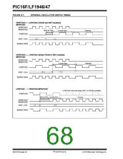
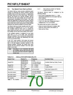
When switching between clock sources, a delay is
required to allow the new clock to stabilize. These oscil-
lator delays are shown in Table 5-1.
5.3.2
OSCILLATOR START-UP TIME-OUT
STATUS (OSTS) BIT
The Oscillator Start-up Time-out Status (OSTS) bit of
the OSCSTAT register indicates whether the system
clock is running from the external clock source, as
defined by the FOSC<2:0> bits in the Configuration
Word 1, or from the internal clock source. In particular,
OSTS indicates that the Oscillator Start-up Timer
(OST) has timed out for LP, XT or HS modes. The OST
does not reflect the status of the Timer1 Oscillator.
2010 Microchip Technology Inc.
Preliminary
DS41414A-page 67

 MICROCHIP [ MICROCHIP ]