PIC16F/LF1946/47
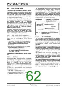
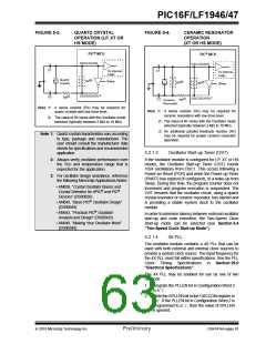
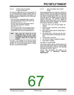
FIGURE 5-3:
QUARTZ CRYSTAL
OPERATION (LP, XT OR
HS MODE)
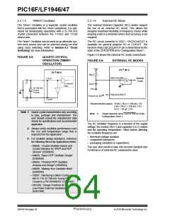
FIGURE 5-4:
CERAMIC RESONATOR
OPERATION
(XT OR HS MODE)
PIC® MCU
PIC® MCU
OSC1/CLKIN
OSC1/CLKIN
C1
C1
To Internal
Logic
To Internal
Logic
Quartz
Crystal
(2)
Sleep
RF
(3)
(2)
RP
RF
Sleep
OSC2/CLKOUT
(1)
C2
RS
OSC2/CLKOUT
(1)
C2
RS
Ceramic
Resonator
Note 1: A series resistor (RS) may be required for
Note 1: A series resistor (RS) may be required for
quartz crystals with low drive level.
ceramic resonators with low drive level.
2: The value of RF varies with the Oscillator mode
selected (typically between 2 M to 10 M.
2: The value of RF varies with the Oscillator mode
selected (typically between 2 M to 10 M.
3: An additional parallel feedback resistor (RP)
may be required for proper ceramic resonator
operation.
Note 1: Quartz crystal characteristics vary according
to type, package and manufacturer. The
user should consult the manufacturer data
sheets for specifications and recommended
application.
5.2.1.3
Oscillator Start-up Timer (OST)
If the oscillator module is configured for LP, XT or HS
modes, the Oscillator Start-up Timer (OST) counts
1024 oscillations from OSC1. This occurs following a
Power-on Reset (POR) and when the Power-up Timer
(PWRT) has expired (if configured), or a wake-up from
Sleep. During this time, the program counter does not
increment and program execution is suspended. The
OST ensures that the oscillator circuit, using a quartz
crystal resonator or ceramic resonator, has started and
is providing a stable system clock to the oscillator
module.
2: Always verify oscillator performance over
the VDD and temperature range that is
expected for the application.
3: For oscillator design assistance, reference
the following Microchip Applications Notes:
• AN826, “Crystal Oscillator Basics and
Crystal Selection for rfPIC® and PIC®
Devices” (DS00826)
• AN849, “Basic PIC® Oscillator Design”
(DS00849)
• AN943, “Practical PIC® Oscillator
In order to minimize latency between external oscillator
start-up and code execution, the Two-Speed Clock
Start-up mode can be selected (see Section 5.4
“Two-Speed Clock Start-up Mode”).
Analysis and Design” (DS00943)
• AN949, “Making Your Oscillator Work”
(DS00949)
5.2.1.4
4X PLL
The oscillator module contains a 4X PLL that can be
used with both external and internal clock sources to
provide a system clock source. The input frequency for
the 4X PLL must fall within specifications. See the PLL
Clock Timing Specifications in Section 29.0
“Electrical Specifications”.
The 4X PLL may be enabled for use by one of two
methods:
1. Program the PLLEN bit in Configuration Word 2
to a ‘1’.
2. Write the SPLLEN bit in the OSCCON register to
a ‘1’. If the PLLEN bit in Configuration Word 2 is
programmed to a ‘1’, then the value of SPLLEN
is ignored.
2010 Microchip Technology Inc.
Preliminary
DS41414A-page 61

 MICROCHIP [ MICROCHIP ]