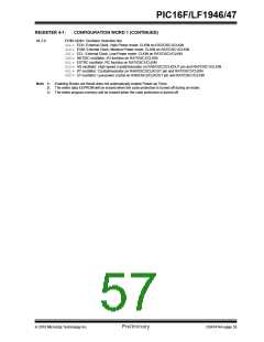
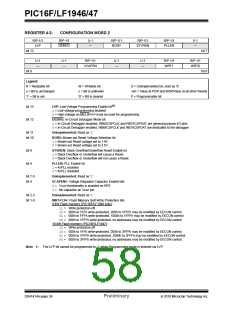
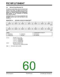
PIC16F/LF1946/47
The oscillator module can be configured in one of six
clock modes.
5.0
5.1
OSCILLATOR MODULE (WITH
FAIL-SAFE CLOCK MONITOR)
1. EC – External clock (ECL, ECM, ECH. See
Section 5.2.1.1 “EC Mode”).
Overview
2. LP – 32 kHz Low-Power Crystal mode.
The oscillator module has a wide variety of clock
sources and selection features that allow it to be used
in a wide range of applications while maximizing perfor-
mance and minimizing power consumption. Figure 5-1
illustrates a block diagram of the oscillator module.
3. XT – Medium Gain Crystal or Ceramic Resonator
Oscillator mode.
4. HS – High Gain Crystal or Ceramic Resonator
mode.
5. RC – External Resistor-Capacitor (RC).
6. INTOSC – Internal oscillator.
Clock sources can be supplied from external oscillators,
quartz crystal resonators, ceramic resonators and
Resistor-Capacitor (RC) circuits. In addition, the system
clock source can be supplied from one of two internal
oscillators and PLL circuits, with a choice of speeds
selectable via software. Additional clock features
include:
Clock Source modes are selected by the FOSC<2:0>
bits in the Configuration Word 1. The FOSC bits
determine the type of oscillator that will be used when
the device is first powered.
The EC clock mode relies on an external logic level
signal as the device clock source. The LP, XT, and HS
clock modes require an external crystal or resonator to
be connected to the device. Each mode is optimized for
a different frequency range. The RC clock mode
requires an external resistor and capacitor to set the
oscillator frequency.
• Selectable system clock source between external
or internal sources via software.
• Two-Speed Start-up mode, which minimizes
latency between external oscillator start-up and
code execution.
• Fail-Safe Clock Monitor (FSCM) designed to
detect a failure of the external clock source (LP,
XT, HS, EC or RC modes) and switch
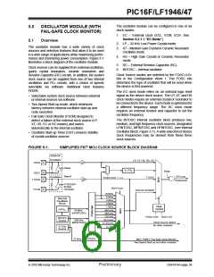
The INTOSC internal oscillator block produces low,
medium, and high frequency clock sources, designated
LFINTOSC, MFINTOSC and HFINTOSC. (see Internal
Oscillator Block, Figure 5-1). A wide selection of device
clock frequencies may be derived from these three
clock sources.
automatically to the internal oscillator.
• Oscillator Start-up Timer (OST) ensures stability
of crystal oscillator sources
FIGURE 5-1:
SIMPLIFIED PIC® MCU CLOCK SOURCE BLOCK DIAGRAM
External
Oscillator
LP, XT, HS, RC, EC
OSC2
Sleep
4 x PLL
Sleep
OSC1
Timer1
CPU and
Oscillator
T1OSC
FOSC<2:0> = 100
T1OSO
Peripherals
T1OSCEN
Enable
Oscillator
IRCF<3:0>
T1OSI
Internal Oscillator
16 MHz
8 MHz
Internal
Oscillator
Block
4 MHz
2 MHz
Clock
1 MHz
Control
HFPLL
500 kHz
250 kHz
125 kHz
62.5 kHz
31.25 kHz
16 MHz
(HFINTOSC)
FOSC<2:0> SCS<1:0>
500 kHz
Source
500 kHz
(MFINTOSC)
Clock Source Option
for other modules
31 kHz
Source
31 kHz
31 kHz (LFINTOSC)
WDT, PWRT, Fail-Safe Clock Monitor
Two-Speed Start-up and other modules
2010 Microchip Technology Inc.
Preliminary
DS41414A-page 59

 MICROCHIP [ MICROCHIP ]