PIC16F/LF1946/47
The Oscillator Start-up Timer (OST) is disabled when
EC mode is selected. Therefore, there is no delay in
operation after a Power-on Reset (POR) or wake-up
from Sleep. Because the PIC® MCU design is fully
static, stopping the external clock input will have the
effect of halting the device while leaving all data intact.
Upon restarting the external clock, the device will
resume operation as if no time had elapsed.
5.2
Clock Source Types
Clock sources can be classified as external or internal.
External clock sources rely on external circuitry for the
clock source to function. Examples are: oscillator mod-
ules (EC mode), quartz crystal resonators or ceramic
resonators (LP, XT and HS modes) and Resis-
tor-Capacitor (RC) mode circuits.
Internal clock sources are contained internally within
the oscillator module. The internal oscillator block has
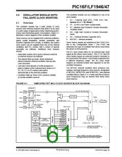
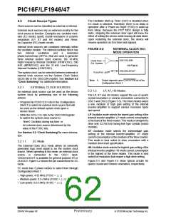
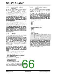
FIGURE 5-2:
EXTERNAL CLOCK (EC)
MODE OPERATION
two
internal
oscillators
and
a
dedicated
phase-locked-loop (HFPLL) that are used to generate
three internal system clock sources: the 16 MHz
High-Frequency Internal Oscillator (HFINTOSC), 500
kHZ (MFINTOSC) and the 31 kHz Low-Frequency
Internal Oscillator (LFINTOSC).
OSC1/CLKIN
PIC® MCU
Clock from
Ext. System
OSC2/CLKOUT
(1)
FOSC/4 or
The system clock can be selected between external or
internal clock sources via the System Clock Select
(SCS) bits in the OSCCON register. See Section 5.3
“Clock Switching” for additional information.
I/O
Note 1: Output depends upon CLKOUTEN bit of the
Configuration Word 1.
5.2.1
EXTERNAL CLOCK SOURCES
5.2.1.2
LP, XT, HS Modes
An external clock source can be used as the device
system clock by performing one of the following
actions:
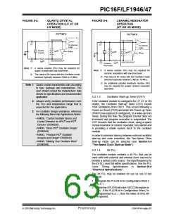
The LP, XT and HS modes support the use of quartz
crystal resonators or ceramic resonators connected to
OSC1 and OSC2 (Figure 5-3). The three modes select
a low, medium or high gain setting of the internal
inverter-amplifier to support various resonator types
and speed.
• Program the FOSC<2:0> bits in the Configuration
Word 1 to select an external clock source that will
be used as the default system clock upon a
device Reset.
LP Oscillator mode selects the lowest gain setting of the
internal inverter-amplifier. LP mode current consumption
is the least of the three modes. This mode is designed to
drive only 32.768 kHz tuning-fork type crystals (watch
crystals).
• Write the SCS<1:0> bits in the OSCCON register
to switch the system clock source to:
- Timer1 Oscillator during run-time, or
- An external clock source determined by the
value of the FOSC bits.
XT Oscillator mode selects the intermediate gain
setting of the internal inverter-amplifier. XT mode
current consumption is the medium of the three modes.
This mode is best suited to drive resonators with a
medium drive level specification.
See Section 5.3 “Clock Switching”for more informa-
tion.
5.2.1.1
EC Mode
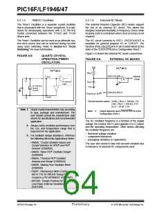
The External Clock (EC) mode allows an externally
generated logic level signal to be the system clock
source. When operating in this mode, an external clock
source is connected to the OSC1 input.
OSC2/CLKOUT is available for general purpose I/O or
CLKOUT. Figure 5-2 shows the pin connections for EC
mode.
HS Oscillator mode selects the highest gain setting of the
internal inverter-amplifier. HS mode current consumption
is the highest of the three modes. This mode is best
suited for resonators that require a high drive setting.
Figure 5-3 and Figure 5-4 show typical circuits for
quartz crystal and ceramic resonators, respectively.
EC mode has 3 power modes to select from through
Configuration Word 1:
• High-power, 4-32 MHz (FOSC = 111)
• Medium power, 0.5-4 MHz (FOSC = 110)
• Low-power, 0-0.5 MHz (FOSC = 101)
DS41414A-page 60
Preliminary
2010 Microchip Technology Inc.

 MICROCHIP [ MICROCHIP ]