PIC16F/LF1946/47
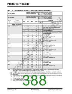
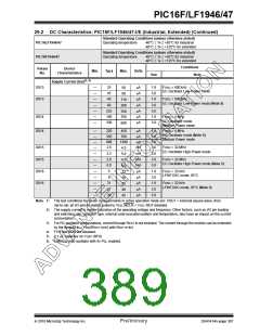
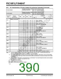
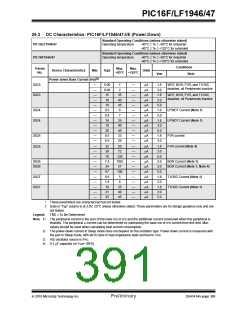
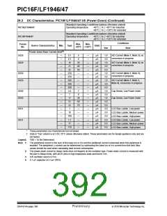
29.3 DC Characteristics: PIC16F/LF1946/47-I/E (Power-Down) (Continued)
Standard Operating Conditions (unless otherwise stated)
PIC16LF1946/47
Operating temperature
-40°C TA +85°C for industrial
-40°C TA +125°C for extended
Standard Operating Conditions (unless otherwise stated)
PIC16F1946/47
Param
Operating temperature
-40°C TA +85°C for industrial
-40°C TA +125°C for extended
Conditions
Max.
Max.
Device Characteristics
Min.
Typ†
Units
No.
+85°C +125°C
VDD
Note
(2)
Power-down Base Current (IPD)
D028
—
—
—
—
—
—
—
—
—
—
—
—
—
—
—
—
—
—
—
—
—
0.1
0.1
16
5
—
—
—
—
—
—
—
—
—
—
—
—
—
—
—
—
—
—
—
—
—
A
A
A
A
A
A
A
A
A
A
A
A
A
A
A
A
A
A
A
A
A
1.8
3.0
1.8
3.0
5.0
1.8
3.0
1.8
3.0
5.0
1.8
3.0
1.8
3.0
5.0
3.0
3.0
3.0
5.0
5.0
5.0
A/D Current (Note 1, Note 3), no
conversion in progress
6
D028
35
40
50
—
—
—
—
—
7
A/D Current (Note 1, Note 3), no
conversion in progress
21
25
D029
D029
250
250
280
280
280
3.5
7
A/D Current (Note 1, Note 3),
conversion in progress
A/D Current (Note 1, Note 3,
Note 4), conversion in progress
D030
D030
Cap Sense, Low Power mode
Cap Sense, Low Power mode
9
17
38
50
70
—
—
—
—
—
—
21
22
D031
D031
1
LCD Bias Ladder, Low-power
LCD Bias Ladder, Medium-power
LCD Bias Ladder, High-power
LCD Bias Ladder, Low-power
LCD Bias Ladder, Medium-power
LCD Bias Ladder, High-power
10
100
1.7
17
170
*
These parameters are characterized but not tested.
†
Data in “Typ” column is at 3.0V, 25°C unless otherwise stated. These parameters are for design guidance only and are
not tested.
Legend:
TBD = To Be Determined
Note 1: The peripheral current is the sum of the base IDD or IPD and the additional current consumed when this peripheral is
enabled. The peripheral current can be determined by subtracting the base IDD or IPD current from this limit. Max
values should be used when calculating total current consumption.
2: The power-down current in Sleep mode does not depend on the oscillator type. Power-down current is measured with
the part in Sleep mode, with all I/O pins in high-impedance state and tied to VDD.
3: A/D oscillator source is FRC.
4: 0.1 F capacitor on VCAP (RF0).
DS41414A-page 390
Preliminary
2010 Microchip Technology Inc.

 MICROCHIP [ MICROCHIP ]