PIC16F/LF1946/47
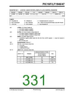
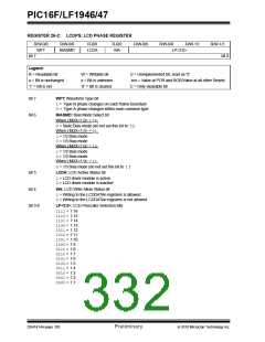
REGISTER 26-2: LCDPS: LCD PHASE REGISTER
R/W-0/0
WFT
R/W-0/0
BIASMD
R-0/0
LCDA
R-0/0
WA
R/W-0/0
R/W-0/0
R/W-1/1
R/W-1/1
bit 0
LP<3:0>
bit 7
Legend:
R = Readable bit
W = Writable bit
x = Bit is unknown
‘0’ = Bit is cleared
U = Unimplemented bit, read as ‘0’
u = Bit is unchanged
‘1’ = Bit is set
-n/n = Value at POR and BOR/Value at all other Resets
C = Only clearable bit
bit 7
bit 6
WFT: Waveform Type bit
1= Type-B phase changes on each frame boundary
0= Type-A phase changes within each common type
BIASMD: Bias Mode Select bit
When LMUX<1:0> = 00:
0= Static Bias mode (do not set this bit to ‘1’)
When LMUX<1:0> = 01:
1= 1/2 Bias mode
0= 1/3 Bias mode
When LMUX<1:0> = 10:
1= 1/2 Bias mode
0= 1/3 Bias mode
When LMUX<1:0> = 11:
0= 1/3 Bias mode (do not set this bit to ‘1’)
LCDA: LCD Active Status bit
bit 5
1= LCD driver module is active
0= LCD driver module is inactive
bit 4
WA: LCD Write Allow Status bit
1= Writing to the LCDDATAn registers is allowed
0= Writing to the LCDDATAn registers is not allowed
bit 3-0
LP<3:0>: LCD Prescaler Selection bits
1111= 1:16
1110= 1:15
1101= 1:14
1100= 1:13
1011= 1:12
1010= 1:11
1001= 1:10
1000= 1:9
0111= 1:8
0110= 1:7
0101= 1:6
0100= 1:5
0011= 1:4
0010= 1:3
0001= 1:2
0000= 1:1
DS41414A-page 330
Preliminary
2010 Microchip Technology Inc.

 MICROCHIP [ MICROCHIP ]