PIC16F/LF1946/47
23.6.1 I2C MASTER MODE OPERATION
2
23.6 I C MASTER MODE
The master device generates all of the serial clock
pulses and the Start and Stop conditions. A transfer is
ended with a Stop condition or with a Repeated Start
condition. Since the Repeated Start condition is also
the beginning of the next serial transfer, the I2C bus will
not be released.
Master mode is enabled by setting and clearing the
appropriate SSPxM bits in the SSPxCON1 register and
by setting the SSPxEN bit. In Master mode, the SCLx
and SDAx lines are set as inputs and are manipulated
by the MSSPx hardware.
Master mode of operation is supported by interrupt
generation on the detection of the Start and Stop con-
ditions. The Stop (P) and Start (S) bits are cleared from
a Reset or when the MSSPx module is disabled. Con-
trol of the I2C bus may be taken when the P bit is set,
or the bus is Idle.
In Master Transmitter mode, serial data is output
through SDAx, while SCLx outputs the serial clock. The
first byte transmitted contains the slave address of the
receiving device (7 bits) and the Read/Write (R/W) bit.
In this case, the R/W bit will be logic ‘0’. Serial data is
transmitted 8 bits at a time. After each byte is transmit-
ted, an Acknowledge bit is received. Start and Stop
conditions are output to indicate the beginning and the
end of a serial transfer.
In Firmware Controlled Master mode, user code
conducts all I2C bus operations based on Start and
Stop bit condition detection. Start and Stop condition
detection is the only active circuitry in this mode. All
other communication is done by the user software
directly manipulating the SDAx and SCLx lines.
In Master Receive mode, the first byte transmitted con-
tains the slave address of the transmitting device
(7 bits) and the R/W bit. In this case, the R/W bit will be
logic ‘1’. Thus, the first byte transmitted is a 7-bit slave
address followed by a ‘1’ to indicate the receive bit.
Serial data is received via SDAx, while SCLx outputs
the serial clock. Serial data is received 8 bits at a time.
After each byte is received, an Acknowledge bit is
transmitted. Start and Stop conditions indicate the
beginning and end of transmission.
The following events will cause the SSPx Interrupt Flag
bit, SSPxIF, to be set (SSPx interrupt, if enabled):
• Start condition detected
• Stop condition detected
• Data transfer byte transmitted/received
• Acknowledge transmitted/received
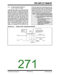
• Repeated Start generated
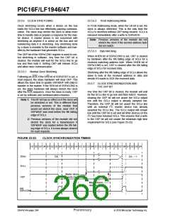
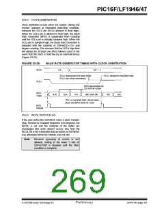
A Baud Rate Generator is used to set the clock
frequency output on SCLx. See Section 23.7 “Baud
Rate Generator” for more detail.
Note 1: The MSSPx module, when configured in
I2C Master mode, does not allow queue-
ing of events. For instance, the user is not
allowed to initiate a Start condition and
immediately write the SSPxBUF register
to initiate transmission before the Start
condition is complete. In this case, the
SSPxBUF will not be written to and the
WCOL bit will be set, indicating that a write
to the SSPxBUF did not occur
2: When in Master mode, Start/Stop detec-
tion is masked and an interrupt is gener-
ated when the SEN/PEN bit is cleared and
the generation is complete.
DS41414A-page 266
Preliminary
2010 Microchip Technology Inc.

 MICROCHIP [ MICROCHIP ]