PIC16F/LF1946/47
20.12 Timer1 Gate Control Register
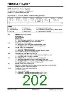
The Timer1 Gate Control register (T1GCON), shown in
Register 20-2, is used to control Timer1 Gate.
REGISTER 20-2: T1GCON: TIMER1 GATE CONTROL REGISTER
R/W-0/u
R/W-0/u
T1GPOL
R/W-0/u
T1GTM
R/W-0/u
R/W/HC-0/u
R-x/x
R/W-0/u
R/W-0/u
TMR1GE
T1GSPM
T1GGO/
DONE
T1GVAL
T1GSS<1:0>
bit 7
bit 0
Legend:
R = Readable bit
W = Writable bit
U = Unimplemented bit, read as ‘0’
u = Bit is unchanged
‘1’ = Bit is set
x = Bit is unknown
‘0’ = Bit is cleared
-n/n = Value at POR and BOR/Value at all other Resets
HC = Bit is cleared by hardware
bit 7
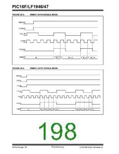
TMR1GE: Timer1 Gate Enable bit
If TMR1ON = 0:
This bit is ignored
If TMR1ON = 1:
1= Timer1 counting is controlled by the Timer1 gate function
0= Timer1 counts regardless of Timer1 gate function
bit 6
bit 5
T1GPOL: Timer1 Gate Polarity bit
1= Timer1 gate is active-high (Timer1 counts when gate is high)
0= Timer1 gate is active-low (Timer1 counts when gate is low)
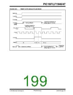
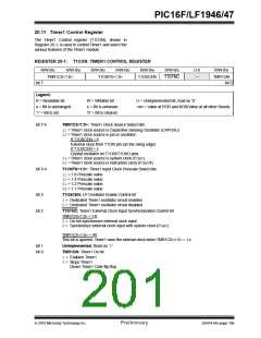
T1GTM: Timer1 Gate Toggle Mode bit
1= Timer1 Gate Toggle mode is enabled
0= Timer1 Gate Toggle mode is disabled and toggle flip flop is cleared
Timer1 gate flip-flop toggles on every rising edge.
bit 4
bit 3
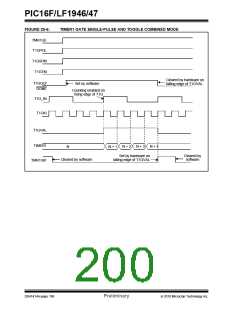
T1GSPM: Timer1 Gate Single-Pulse Mode bit
1= Timer1 gate Single-Pulse mode is enabled and is controlling Timer1 gate
0= Timer1 gate Single-Pulse mode is disabled
T1GGO/DONE: Timer1 Gate Single-Pulse Acquisition Status bit
1= Timer1 gate single-pulse acquisition is ready, waiting for an edge
0= Timer1 gate single-pulse acquisition has completed or has not been started
This bit is automatically cleared when T1GSPM is cleared.
bit 2
T1GVAL: Timer1 Gate Current State bit
Indicates the current state of the Timer1 gate that could be provided to TMR1H:TMR1L.
Unaffected by Timer1 Gate Enable (TMR1GE).
bit 1-0
T1GSS<1:0>: Timer1 Gate Source Select bits
00= Timer1 Gate pin
01= Timer0 overflow output
10= Comparator 1 optionally synchronized output (SYNCC1OUT)
11= Comparator 2 optionally synchronized output (SYNCC2OUT)
DS41414A-page 200
Preliminary
2010 Microchip Technology Inc.

 MICROCHIP [ MICROCHIP ]