PIC16F/LF1946/47
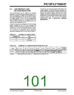
On power-up, the external capacitor will load the LDO
voltage regulator. To prevent erroneous operation, the
device is held in Reset while a constant current source
charges the external capacitor. After the cap is fully
charged, the device is released from Reset. For more
information on recommended capacitor values and the
constant current rate, refer to the LDO Regulator
Characteristics Table in Section 29.0 “Electrical
Specifications”.
8.0
LOW DROPOUT (LDO)
VOLTAGE REGULATOR
The PIC16F1946/47 has an internal Low Dropout
Regulator (LDO) which provides operation above 3.6V.
The LDO regulates a voltage for the internal device
logic while permitting the VDD and I/O pins to operate
at a higher voltage. There is no user enable/disable
control available for the LDO, it is always active. The
PIC16LF1946/47 operates at a maximum VDD of 3.6V
and does not incorporate an LDO.
A device I/O pin may be configured as the LDO voltage
output, identified as the VCAP pin. Although not
required, an external low-ESR capacitor may be con-
nected to the VCAP pin for additional regulator stability.
The VCAPEN bit of Configuration Word 2 determines
which pin is assigned as the VCAP pin. Refer to Table 8-1.
TABLE 8-1:
VCAPEN<1:0>
00
11
VCAPEN<1:0> SELECT BITS
Pin
RF0
No Vcap
TABLE 8-2:
SUMMARY OF CONFIGURATION WORD WITH LDO
Register
on Page
Name
Bits
Bit -/7
Bit -/6
Bit 13/5
Bit 12/4
Bit 11/3
Bit 10/2
Bit 9/1
Bit 8/0
13:8
7:0
—
—
—
—
LVP
DEBUG
—
—
—
BORV
—
STVREN
WRT1
PLLEN
WRT0
CONFIG2
56
VCAPEN1
Legend:
— = unimplemented locations read as ‘0’. Shaded cells are not used by LDO.
2010 Microchip Technology Inc.
Preliminary
DS41414A-page 99

 MICROCHIP [ MICROCHIP ]