MCP7940M
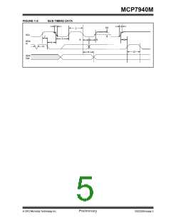
TABLE 1-2:
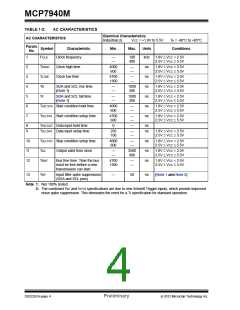
AC CHARACTERISTICS
Electrical Characteristics:
AC CHARACTERISTICS
Industrial (I):
VCC = +1.8V to 5.5V
TA = -40°C to +85°C
Param.
Symbol
No.
Characteristic
Clock frequency
Min.
Max.
Units
Conditions
1
2
3
4
5
6
7
FCLK
THIGH
TLOW
TR
—
—
100
400
kHz
1.8V VCC < 2.5V
2.5V VCC 5.5V
Clock high time
Clock low time
4000
600
—
—
ns
ns
ns
ns
ns
ns
1.8V VCC < 2.5V
2.5V VCC 5.5V
4700
1300
—
—
1.8V VCC < 2.5V
2.5V VCC 5.5V
SDA and SCL rise time
(Note 1)
—
—
1000
300
1.8V VCC < 2.5V
2.5V VCC 5.5V
TF
SDA and SCL fall time
(Note 1)
—
—
1000
300
1.8V VCC < 2.5V
2.5V VCC 5.5V
THD:STA Start condition hold time
TSU:STA Start condition setup time
4000
600
—
—
1.8V VCC < 2.5V
2.5V VCC 5.5V
4700
600
—
—
1.8V VCC < 2.5V
2.5V VCC 5.5V
8
9
THD:DAT Data input hold time
TSU:DAT Data input setup time
0
—
ns
ns
250
100
—
—
1.8V VCC < 2.5V
2.5V VCC 5.5V
10
11
12
TSU:STO Stop condition setup time
4000
600
—
—
ns
ns
ns
1.8V VCC < 2.5V
2.5V VCC 5.5V
TAA
Output valid from clock
—
—
3500
900
1.8V VCC < 2.5V
2.5V VCC 5.5V
TBUF
Bus free time: Time the bus
must be free before a new
transmission can start
4700
1300
—
—
1.8V VCC < 2.5V
2.5V VCC 5.5V
13
TSP
Input filter spike suppression
(SDA and SCL pins)
—
50
ns
(Note 1 and Note 2)
Note 1: Not 100% tested.
2: The combined TSP and VHYS specifications are due to new Schmitt Trigger inputs, which provide improved
noise spike suppression. This eliminates the need for a TI specification for standard operation.
DS22292A-page 4
Preliminary
2012 Microchip Technology Inc.

 MICROCHIP [ MICROCHIP ]