MCP414X/416X/424X/426X
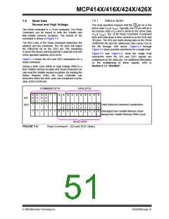
7.8.1
SINGLE DECREMENT
7.8
Decrement Wiper
Normal and High Voltage
Typically the CS pin starts at the inactive state (VIH), but
may be already be in the active state due to the
completion of another command.
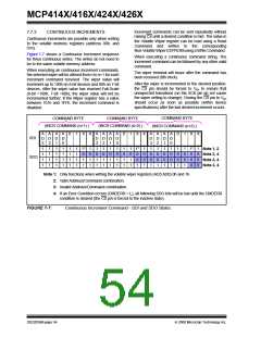
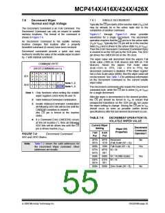
The Decrement Command is an 8-bit command. The
Decrement Command can only be issued to volatile
memory locations. The format of the command is
shown in Figure 7-6.
Figure 6-7 through Figure 6-8 show possible
waveforms for a single Decrement. The decrement
operation requires that the CS pin be in the active state
(VILor VIHH). Typically the CS pin will be in the inactive
state (VIH) and is driven to the active state (VILor VIHH).
Then the 8-bit Decrement Command (Command Byte)
is clocked in on the SDI pin by the SCK pins. The SDO
pin drives the CMDERR bit on the 7th clock.
An Decrement Command to the volatile memory
location changes that location after
formatted command (8-clocks) have been received.
a properly
Decrement commands provide a quick and easy
method to modify the value of the volatile wiper location
by -1 with minimal overhead.
The wiper value will decrement from the wipers Full
Scale value (100h on 8-bit devices and 80h on 7-bit
devices). Above the wipers Full Scale value
(8-bit =101h to 1FFh, 7-bit = 81h to FFh), the
decrement command is disabled. If the Wiper register
has a Zero Scale value (000h), then the wiper value will
not decrement. See Table 7-4 for additional information
on the Decrement Command vs. the current volatile
wiper value.
COMMAND BYTE
(DECR COMMAND (n+1))
A
D
3
A
D
2
A
D
1
A
D
0
1
0
X
X
SDI
1
1
1
1
1
1
1
1
1
1
1
1
1*
0
1
0
Note 1, 2
Note 1, 3
SDO
The Decrement commands only require the Decrement
command byte, while the CS pin is active (VILor VIHH
)
Note 1: Only functions when writing the volatile
for a single decrement.
wiper registers (AD3:AD0) 0h and 1h.
After the wiper is decremented to the desired position,
the CS pin should be forced to VIH to ensure that
unexpected transitions on the SCK pin do not cause
the wiper setting to change. Driving the CS pin to VIH
should occur as soon as possible (within device
specifications) after the last desired decrement occurs.
2: Valid Address/Command combination.
3: Invalid Address/Command combination
all following SDO bits will be low until the
CMDERR condition is cleared.
(the CS pin is forced to the inactive
state).
TABLE 7-5:
DECREMENT OPERATION VS.
VOLATILE WIPER VALUE
4: If a Command Error (CMDERR) occurs
at this bit location (*), then all following
SDO bits will be driven low until the CS
pin is driven inactive (VIH).
Current Wiper
Setting
Decrement
Wiper (W)
Command
Properties
7-bit
Pot
8-bit
Pot
Operates?
FIGURE 7-8:
Decrement Command -
SDI and SDO States.
3FFh
081h
3FFh Reserved
101h (Full-Scale (W = A))
No
Note:
Table 7-2 shows the valid addresses for
the Decrement Wiper command. Other
addresses are invalid.
080h
100h Full-Scale (W = A)
Yes
07Fh
041h
0FFh W = N
081
040h
080h W = N (Mid-Scale)
Yes
No
03Fh
001h
07Fh W = N
001
000h
000h Zero Scale (W = B)
© 2008 Microchip Technology Inc.
DS22059B-page 55

 MICROCHIP [ MICROCHIP ]