MCP2515
When in Sleep mode, the MCP2515 stops its internal
oscillator. The MCP2515 will wake-up when bus activity
occurs or when the MCU sets, via the SPI interface, the
CANINTF.WAKIF bit to ‘generate’ a wake-up attempt
(the CANINTE.WAKIE bit must also be set in order for
the wake-up interrupt to occur).
10.0 MODES OF OPERATION
The MCP2515 has five modes of operation. These
modes are:
1. Configuration mode.
2. Normal mode.
The TXCAN pin will remain in the recessive state while
the MCP2515 is in Sleep mode.
3. Sleep mode.
4. Listen-only mode.
5. Loopback mode.
10.2.1
WAKE-UP FUNCTIONS
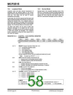
The operational mode is selected via the
CANCTRL. REQOP bits (see Register 10-1).
The device will monitor the RXCAN pin for activity while
it is in Sleep mode. If the CANINTE.WAKIE bit is set,
the device will wake up and generate an interrupt.
Since the internal oscillator is shut down while in Sleep
mode, it will take some amount of time for the oscillator
to start up and the device to enable itself to receive
messages. This Oscillator Start-up Timer (OST) is
defined as 128 TOSC.
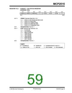
When changing modes, the mode will not actually
change until all pending message transmissions are
complete. The requested mode must be verified by
reading
the
CANSTAT.OPMODE
bits
(see
Register 10-2).
10.1 Configuration Mode
The device will ignore the message that caused the
wake-up from Sleep mode, as well as any messages
that occur while the device is ‘waking up’. The device
will wake up in Listen-only mode. The MCU must set
Normal mode before the MCP2515 will be able to
communicate on the bus.
The MCP2515 must be initialized before activation.
This is only possible if the device is in the Configuration
mode. Configuration mode is automatically selected
after power-up, a reset or can be entered from any
other mode by setting the CANTRL.REQOP bits to
‘100’. When Configuration mode is entered, all error
counters are cleared. Configuration mode is the only
mode where the following registers are modifiable:
The device can be programmed to apply a low-pass
filter function to the RXCAN input line while in internal
Sleep mode. This feature can be used to prevent the
device from waking up due to short glitches on the CAN
bus lines. The CNF3.WAKFIL bit enables or disables
the filter.
• CNF1, CNF2, CNF3
• TXRTSCTRL
• Filter registers
• Mask registers
10.3 Listen-only Mode
Listen-only mode provides a means for the MCP2515
to receive all messages (including messages with
errors) by configuring the RXBnCTRL.RXM<1:0> bits.
This mode can be used for bus monitor applications or
for detecting the baud rate in ‘hot plugging’ situations.
10.2 Sleep Mode
The MCP2515 has an internal Sleep mode that is used
to minimize the current consumption of the device. The
SPI interface remains active for reading even when the
MCP2515 is in Sleep mode, allowing access to all
registers.
For auto-baud detection, it is necessary that there are
at least two other nodes that are communicating with
each other. The baud rate can be detected empirically
by testing different values until valid messages are
received.
To enter Sleep mode, the mode request bits are set in
the CANCTRL register (REQOP<2:0>). The
CANSTAT.OPMODE bits indicate operation mode.
These bits should be read after sending the sleep
command to the MCP2515. The MCP2515 is active
and has not yet entered Sleep mode until these bits
indicate that Sleep mode has been entered.
Listen-only mode is a silent mode, meaning no
messages will be transmitted while in this mode
(including error flags or acknowledge signals). The
filters and masks can be used to allow only particular
messages to be loaded into the receive registers, or the
masks can be set to all zeros to allow a message with
any identifier to pass. The error counters are reset and
deactivated in this state. The Listen-only mode is
activated by setting the mode request bits in the
CANCTRL register.
When in internal Sleep mode, the wake-up interrupt is
still active (if enabled). This is done so that the MCU
can also be placed into a Sleep mode and use the
MCP2515 to wake it up upon detecting activity on the
bus.
© 2005 Microchip Technology Inc.
Preliminary
DS21801D-page 57

 MICROCHIP [ MICROCHIP ]