MCP2515
9.0
RESET
The MCP2515 differentiates between two resets:
1. Hardware Reset – Low on RESET pin.
2. SPI Reset – Reset via SPI command.
Both of these resets are functionally equivalent. It is
important to provide one of these two resets after
power-up to ensure that the logic and registers are in
their default state. A hardware reset can be achieved
automatically by placing an RC on the RESET pin. (see
Figure 9-1). The values must be such that the device is
held in reset for a minimum of 2 µs after VDD reaches
operating voltage, as indicated in the electrical
specification (tRL).
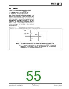
FIGURE 9-1:
RESET PIN CONFIGURATION EXAMPLE
VDD
VDD
D(1)
R
R1(2)
RESET
C
Note 1: The diode D helps discharge the capacitor quickly when VDD powers down.
2: R1 = 1 kΩ to 10 kΩ will limit any current flowing into RESET from external
capacitor C, in the event of RESET pin breakdown due to Electrostatic
Discharge (ESD) or Electrical Overstress (EOS).
© 2005 Microchip Technology Inc.
Preliminary
DS21801D-page 55

 MICROCHIP [ MICROCHIP ]